Improved injector arrangement for diesel engines using slurry or emulsion fuels
a diesel type and injector technology, applied in the direction of machines/engines, combustion types, lighting and heating apparatus, etc., can solve the problems of increasing the volume of fuel occupying the pump, and achieve the effect of reducing or eliminating residual diesel fuel, facilitating fast and thorough fuel flushing, and reducing viscosity
- Summary
- Abstract
- Description
- Claims
- Application Information
AI Technical Summary
Benefits of technology
Problems solved by technology
Method used
Image
Examples
first embodiment
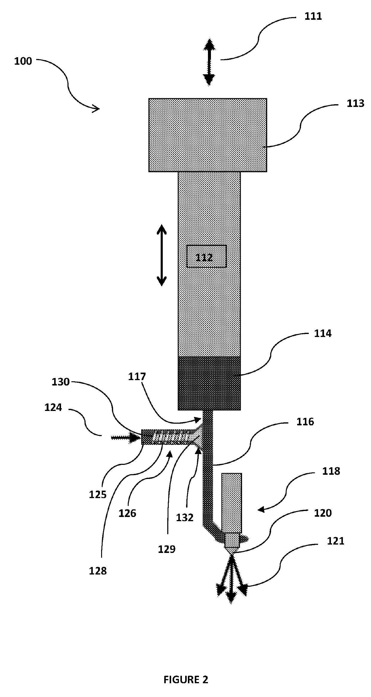
[0067]Turning now to FIG. 2, there is illustrated a fuel injection arrangement 100 according to the present invention. Arrangement 100 includes an injector nozzle 120 for injecting a fuel spray 121 into a combustion chamber (not shown). Injector nozzle 120 is part of a larger injector nozzle assembly 118 which includes an internal spring-loaded and normally closed nozzle valve (not shown) configured to open when pressure in the upstream fuel line increases to a predetermined valve opening pressure. Upon opening of the normally closed nozzle valve, fuel spray 121 is injected into the combustion chamber until the subsequent reduction in upstream fuel line pressure reduces below the nozzle valve opening pressure whereupon the nozzle valve returns to its normally closed position and fuel spray 121 into the combustion chamber is terminated until the next injection event.
[0068]The fuel line immediately upstream of the injector nozzle assembly 118 comprises a fuel duct 116 communicating be...
second embodiment
[0073]FIG. 3 illustrates the present invention comprising fuel injection arrangement 200 which provides a variation on the arrangement of check valve 126 illustrated and described above with respect to FIG. 2. Arrangement 200 includes a check valve 226 comprising a spring-loaded normally-closed poppet valve similar to the arrangement of check valve 126 in FIG. 2 except that valve stem 228 and helical spring 230 are locate outside of the fuel supply 224 which communicates with a small fuel chamber 236 located behind valve seat 232 and upstream of valve head 229. Valve stem 228 extends through an opening in the fuel inlet chamber 236. Seal oil 234 is applied to valve stem 228 within a stem housing (not shown) at higher pressure than the fuel within the fuel inlet chamber 236 to prevent fuel ingress from the inlet chamber 236 into the stem housing. This form of the invention advantageously isolates the valve stem 228 and valve spring 230 from the fuel supply 224 further reducing the po...
third embodiment
[0074]FIG. 4 illustrates a fuel injection arrangement 300 comprising the present invention. In contrast to the spring-loaded poppet valves of previous injection arrangements 100 and 200, arrangement 300 includes a check valve comprised of a floating ball check valve 326. In alternative embodiments of the present invention, check valve 326 could comprise alternative floating check valves such as a floating poppet valve. As illustrated in FIG. 4, ball check valve 326 includes a floating ball 329 normally seated in valve seat 332 and retained therein by the pressure differential between the injection path and the fuel inlet conduit 325. An extendable follower 338 is located adjacent to ball 329 limiting the range of movement of ball 329. In particular embodiments, the follower is spring-loaded to urge the ball toward the valve seat. A decrease in pressure within the injection path on the downstream side of check valve 326 causes floating ball 329 to unseat from valve seat 332 and there...
PUM
 Abstract
Description
Claims
Application Information
 - R&D
- Intellectual Property
- Life Sciences
- Materials
- Tech Scout
- Unparalleled Data Quality
- Higher Quality Content
- 60% Fewer Hallucinations
Browse by: Latest US Patents, China's latest patents, Technical Efficacy Thesaurus, Application Domain, Technology Topic, Popular Technical Reports.
© 2025 PatSnap. All rights reserved.Legal|Privacy policy|Modern Slavery Act Transparency Statement|Sitemap|About US| Contact US: help@patsnap.com


