
Local oscillator distribution for a millimeter wave semiconductor device

Active Publication Date: 2019-06-20
GLOBALFOUNDRIES US INC
View PDF2 Cites 0 Cited by
  • Summary
  • Abstract
  • Description
  • Claims
  • Application Information

AI Technical Summary

Benefits of technology

This patent is about CMOS gain elements and devices made up of those elements. These elements can create smaller and more energy-efficient power dividers and repeaters. The technical effect is that CMOS gain elements can make components more efficient and compact.

Problems solved by technology

Implementing mm-wave applications produces many challenges when designing circuits for these applications.
Also, given that power is lost with distance of signal transmission, repeaters may be needed to boost the signal power.
The Wilkinson power divider, however, has a relatively large footprint and, because it is a passive divider, suffers from signal loss and accordingly requires amplification.
Use of an amplifier with the Wilkinson power divider entails relatively large energy consumption characteristics.
Other power dividers, such as the Gysel power divider, and repeaters known in the art also have relatively large footprints and relatively large energy consumption characteristics.
The inclusion of transformers and related circuits increases silicon die area and therefore cost.

Method used


Image

  • Local oscillator distribution for a millimeter wave semiconductor device
  • Local oscillator distribution for a millimeter wave semiconductor device
  • Local oscillator distribution for a millimeter wave semiconductor device

Examples


Embodiment Construction

[0029]Various illustrative embodiments of the invention are described below. In the interest of clarity, not all features of an actual implementation are described in this specification. It will of course be appreciated that in the development of any such actual embodiment, numerous implementation-specific decisions must be made to achieve the developers' specific goals, such as compliance with system-related and business-related constraints, which will vary from one implementation to another. Moreover, it will be appreciated that such a development effort might be complex and time-consuming, but would nevertheless be a routine undertaking for those of ordinary skill in the art having the benefit of this disclosure.

[0030]The present subject matter will now be described with reference to the attached figures. Various structures, systems, and devices are schematically depicted in the drawings for purposes of explanation only and so as to not obscure the present disclosure with details...


PUM


Abstract

A CMOS gain element is disclosed herein. Also disclosed herein are splitters, comprising the CMOS gain element, and local oscillator distribution circuitry comprising the splitters and the CMOS gain elements. Semiconductor devices comprising the local oscillator distribution circuitry may have smaller footprints and reduced power consumption relative to prior art devices.

Description

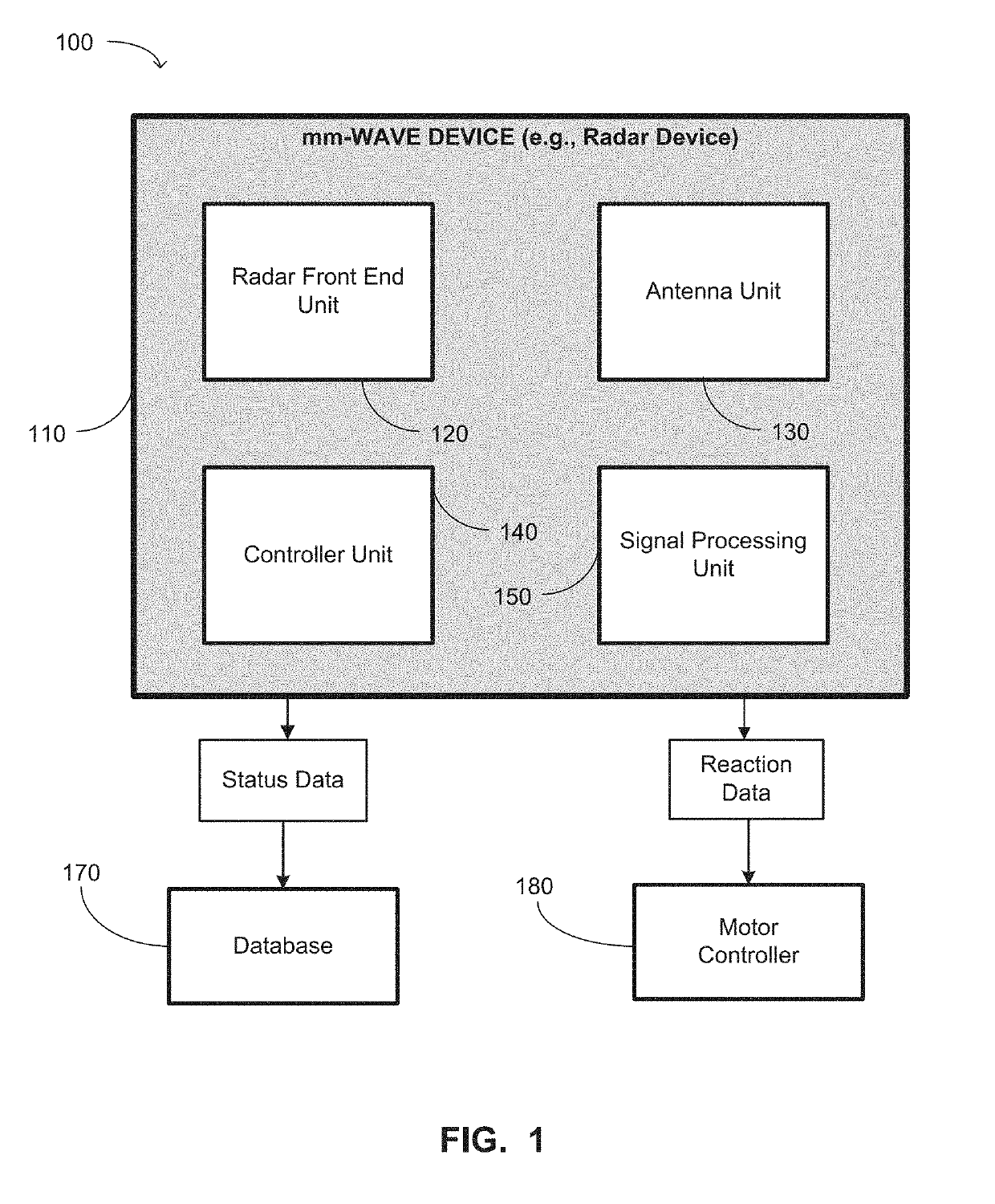
BACKGROUND OF THE INVENTIONField of the Invention[0001]Generally, the present disclosure relates to sophisticated semiconductor devices and, more specifically, to distribution of a mm-wave local oscillator signal, CMOS gain element, and semiconductor devices comprising the same.Description of the Related Art[0002]In an effort to maintain Moore's Law as a self-fulfilling prophecy, the semiconductor industry in recent years has sought to reduce the sizes of semiconductor devices. Also, in an effort to reduce operating expenses of semiconductor device, the semiconductor industry in recent years has sought to reduce the energy consumption of semiconductor devices. This is particularly a concern in semiconductor devices that operate in the millimeter wave (mm-wave) range.[0003]Semiconductor devices that involve mm-wave applications include devices that operate based on the electromagnetic spectrum of radio band frequencies in the range of about 30 GigaHertz (GHz) to about 300 GHz. The mm...

Claims


Application Information

Patent Timeline
IPC IPC(8): H03B1/02H03B5/12H03H11/36H01P5/16
CPCH03B1/02H03B5/1203H03H11/36H01P5/16G06F1/10H01P5/12H04B1/525G06F1/08H04B1/38
Inventor BELLAOUAR, ABDELLATIFBALASUBRAMANIYAN, ARUL
Owner GLOBALFOUNDRIES US INC
Learn More