Sheet for heat bonding, and sheet for heat bonding having dicing tape

a technology of heat bonding and dicing tape, which is applied in the direction of film/foil adhesives without carriers, film/foil adhesives, synthetic resin layered products, etc., can solve the problems of heat characteristics and reliability in solder and electrically conductive adhesives, and achieve high adhesion and strengthen the bonding after sintering

Active Publication Date: 2019-06-20
NITTO DENKO CORP
View PDF0 Cites 3 Cited by
  • Summary
  • Abstract
  • Description
  • Claims
  • Application Information

AI Technical Summary

Benefits of technology

[0025]The sheet for heat bonding having dicing tape allows a step of laminating the sheet for heat bonding to the dicing tape to be omitted since the sheet for heat bonding is integrated with the dicing tape. The adhesive layer is present, whereby, by laminating the object to be bonded to the adhesive layer, the object to be bonded can be firmly fixed to the sheet for heat bonding before sintering. The sheet for heat bonding includes the adhesive layer, whereby the adhesion before sintering of the pre-sintering layer with respect to the object to be bonded may not be considered. As a result, as the pre-sintering layer, a composition serving as a strengthened sintered layer after sintering can be adopted. As described above, according to the sheet for heat bonding having dicing tape according to the present invention, high adhesion before sintering with respect to the object to be bonded can be achieved, and the bonding after sintering can be strengthened.

Problems solved by technology

Therefore, an electrically conductive adhesive used for the power semiconductor device desirably has high heat dissipation properties and low electric resistivity.
This causes problems in heat characteristics and reliability in solder and an electrically conductive adhesive as conventional bonding and adhesive materials.

Method used


Image

  • Sheet for heat bonding, and sheet for heat bonding having dicing tape
  • Sheet for heat bonding, and sheet for heat bonding having dicing tape

Examples


example 1

[0203]

[0204]A solution (12 wt %) prepared by previously dissolving a thermally decomposable binder A in MEK at a weight ratio of 1:1, a low boiling point binder A (4 wt %), metal fine particles A (60 wt %), and an organic solvent A (24% by weight) were placed in a stirring pot of a hybrid mixer (HM-500, manufactured by Keyence Corporation), and stirred and mixed in a stirring mode for 3 minutes.

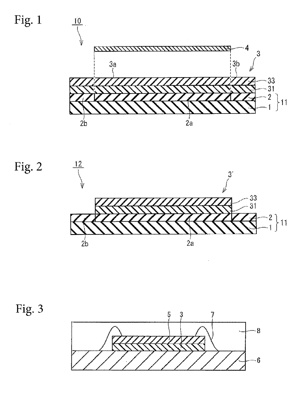
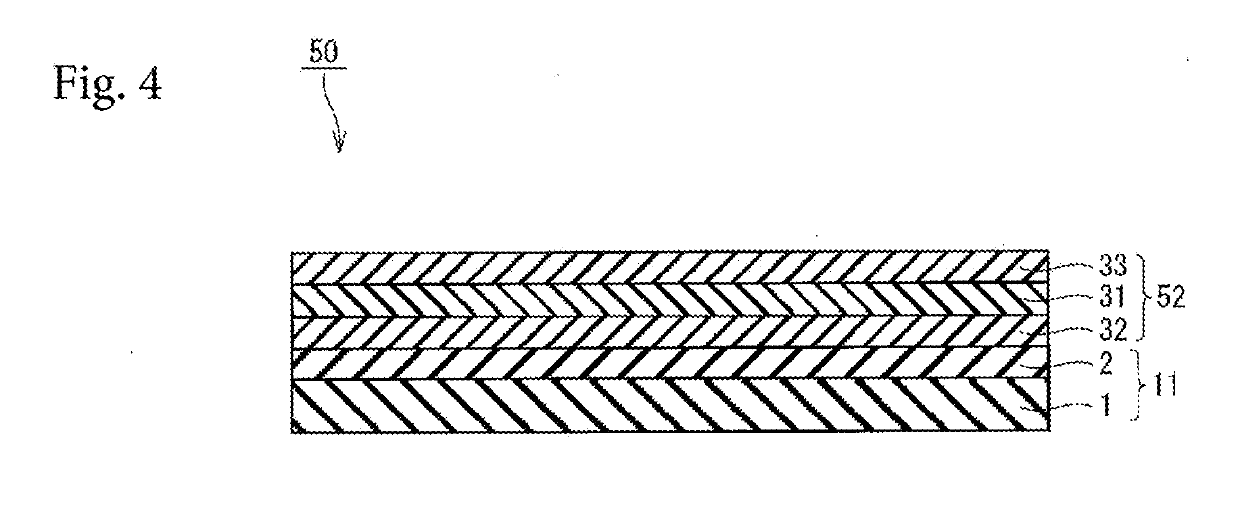
[0205]The varnish thus obtained was applied to a release-treated film (MRA 38 manufactured by Mitsubishi Plastics Co., Ltd.) so as to have a thickness after drying of 70 μm, and dried to obtain a pre-sintering layer A. The drying was performed at 80° C. for 2 minutes.

[0206]

[0207]A solution (40% by weight) prepared by previously dissolving a thermally decomposable binder A in MEK at a weight ratio of 1:1, a low boiling point binder A (13% by weight), metal fine particles A (30% by weight), and an organic solvent A (17% by weight) were placed in a stirring pot of a hybrid mixer (HM-500, manufac...

example 2

[0235]

[0236]For the pre-sintering layer, the same pre-sintering layer A as that in Example 1 was used.

[0237]

[0238]For the adhesive layer, the same adhesive layer A as that in Example 1 was used.

[0239]

[0240]A solution (50% by weight) obtained by previously dissolving a thermally decomposable binder A in MEK at a weight ratio of 1:1 and an organic solvent A (50% by weight) were placed in a stirring pot of a hybrid mixer (HM-500 manufactured by Keyence Corporation), and stirred and mixed in a stirring mode for 3 minutes.

[0241]The obtained varnish was applied to a release-treated film (MRA 38 manufactured by Mitsubishi Plastics Co., Ltd.) so as to have a thickness after drying of 6 μm, and dried to obtain a component migration prevention layer A. The drying was carried out at 80° C. for 2 minutes.

[0242]

[0243]First, the coating dried surfaces of the pre-sintering layer A and component migration prevention layer A were made to face each other, and laminated to each other at 70° C. with a ...


PUM

PropertyMeasurementUnit
thicknessaaaaaaaaaa
temperatureaaaaaaaaaa
thicknessaaaaaaaaaa

Abstract

A sheet for heat bonding, having a pre-sintering layer that becomes a sintered layer by being heated, and an adhesion layer.

Description

TECHNICAL FIELD[0001]The present invention relates to a sheet for heat bonding and a sheet for heat bonding having dicing tape.BACKGROUND ART[0002]In the manufacture of a semiconductor device, a method for bonding a semiconductor element to an adherend such as a metal lead frame (a so-called die bonding method) has been developed from a conventional method for using gold-silicon eutectic bonding to a method for using solder or a resin paste. At the present time, an electrically conductive resin paste may be used.[0003]In recent years, a power semiconductor device for controlling and supplying electric power has been remarkably widely used. Since a current always flows in the power semiconductor device, the power semiconductor device has a large heat value. Therefore, an electrically conductive adhesive used for the power semiconductor device desirably has high heat dissipation properties and low electric resistivity.[0004]Low loss and a high-speed operation are required for the powe...

Claims


Application Information

Patent Timeline
Patent Type & Authority Applications(United States)
IPC IPC(8): B22F3/02H01L21/52H01L21/683H01L21/304C09J7/10
CPCB22F3/02H01L21/52H01L21/6836H01L21/3043C09J7/10H01L2221/68327H01L2221/68381H01L2924/181H01L2224/48091H01L2224/73265B32B7/12B32B27/36B32B27/365C09J9/02C09J11/04C23C28/00C23C28/04C23C28/30C23C28/34C09J7/30C08K2201/001C09J2203/326C09J7/22C09J133/066B32B5/02B32B5/16B32B5/30B32B15/16B32B23/12B32B27/14B32B29/04B32B2250/44B32B23/20B32B27/306B32B27/32B32B27/308B32B27/40B32B27/281B32B27/285B32B27/288B32B27/34B32B27/304B32B27/283B32B2260/046B32B2262/101B32B2264/105B32B2307/732B32B2405/00H01L2224/8384H01L2224/27002H01L2224/27436C09J2301/41C09J2301/408C08F220/1808H01L2924/00014H01L2924/00012C08F220/20B32B27/08
Inventor HONDA, SATOSHISUGO, YUKISHIMODA, MAYU
Owner NITTO DENKO CORP
Why Eureka
Try Eureka