
Pinless femoral tracking

a technology of femoral tracking and pins, applied in the field of computer assisted surgery, can solve the problems of reduced functionality, increased surgery rate, and worse outcomes, and achieve the effect of reducing the difficulty of creating bone cuts to correctly align the implants, and reducing the accuracy of femoral positioning

Inactive Publication Date: 2019-06-13
THINK SURGICAL
View PDF0 Cites 4 Cited by
  • Summary
  • Abstract
  • Description
  • Claims
  • Application Information

AI Technical Summary

Benefits of technology

The patent describes a surgical system that uses a brace and fiducial markers to track the position and orientation of a subject's bone during a procedure. The system includes single-LED markers that are inserted into the bone. The tracking system uses these markers to compensate for any remaining degrees of freedom between the brace and the bone, and the system also stores the position and orientation of reference features on the brace. The computing system is programmed to detect any motion between the reference features and the markers, and notify the user if any motion is detected. Overall, the system improves the accuracy and efficiency of surgical procedures involving bones.

Problems solved by technology

Even small implant alignment errors outside of clinically acceptable ranges correlate to significantly worse outcomes that are associated with increased rates of revision surgery.
In TKA, creating the bone cuts to correctly align the implants is especially difficult because the femur requires at least five planar bone cuts to receive the femoral prosthesis.
Mal-alignment in any one of these planar cuts or orientations may have drastic consequences on the final result of the procedure and the wear pattern of the implant, resulting in reduced functionality and decreased implant longevity.
The securement of pins and screws is time-consuming and invasive.
Additionally, such pins and screws, which are typically greater than 3.2 mm in diameter, may induce tissue trauma that can result in bone fracture.

Method used


Image

  • Pinless femoral tracking
  • Pinless femoral tracking
  • Pinless femoral tracking

Examples


Embodiment Construction

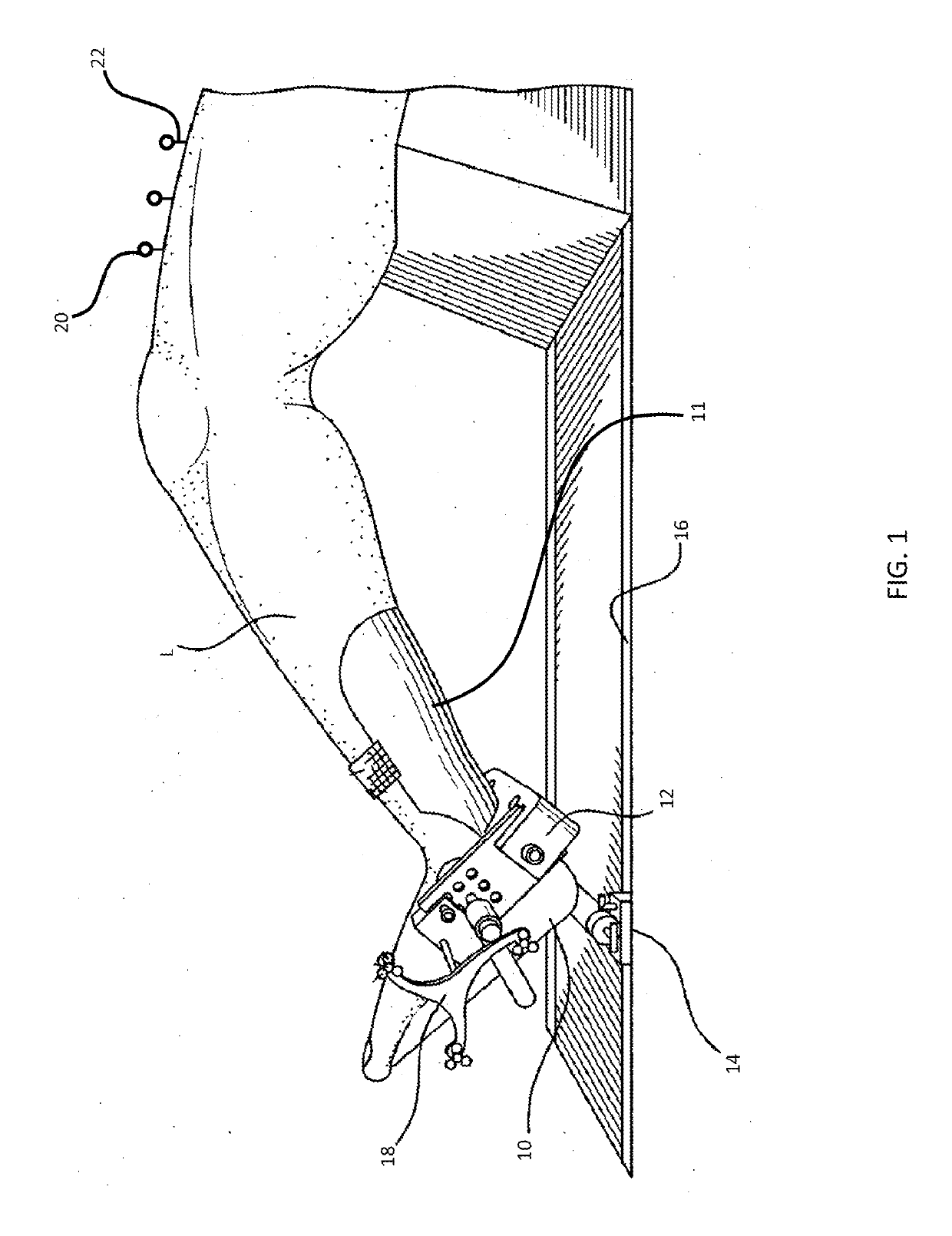
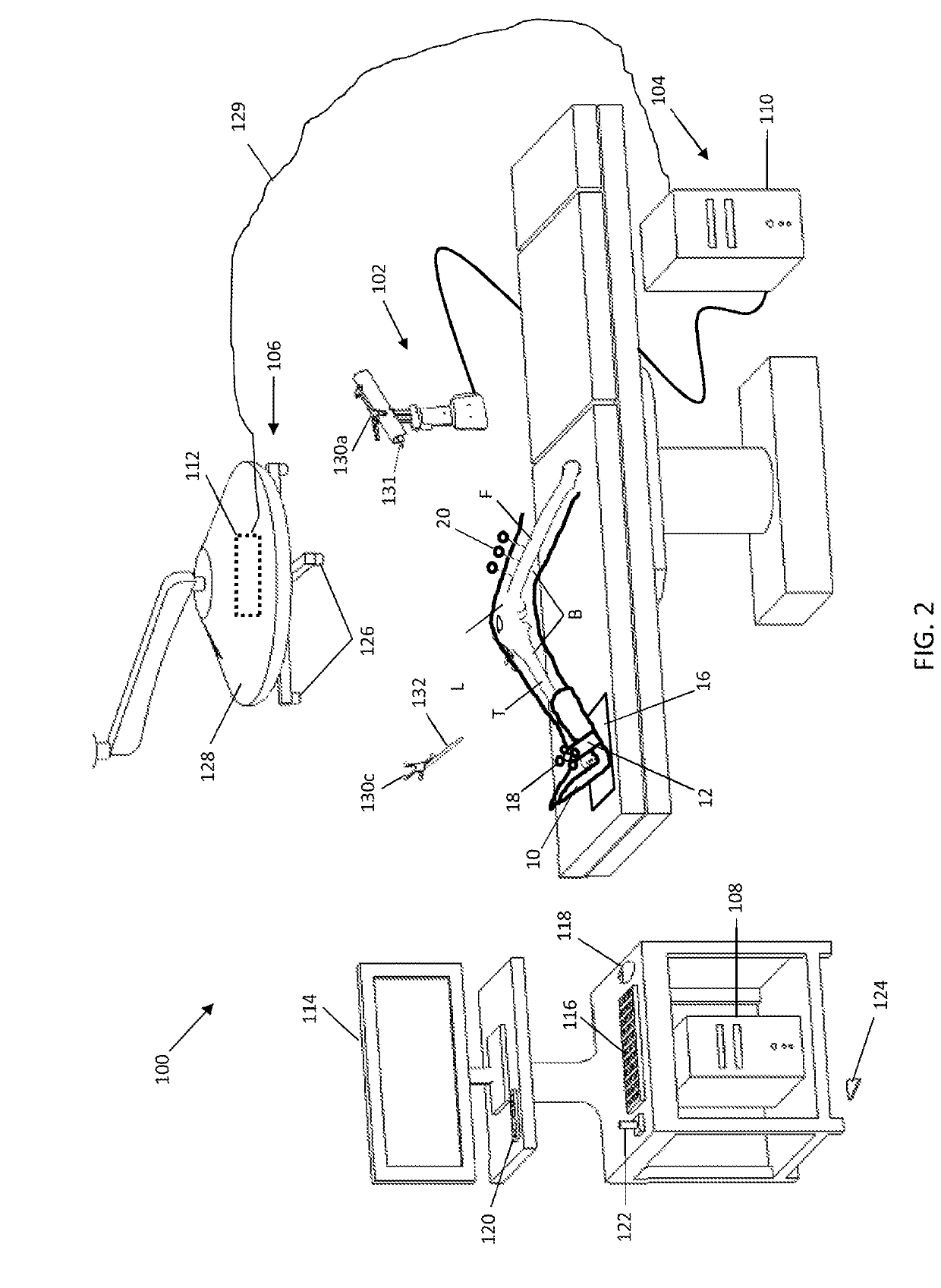
[0015]The present invention has utility as a system and method to optically track a subject's anatomy during a procedure without the need for the use of invasive pins and screws currently used to support and attach six-degree-of-freedom fiducial arrays directly to the bone. The system and method is especially advantageous for surgical procedures involving brittle or osteoporotic bone or any other procedure where the preservation of surrounding healthy bone is desirable. In particular, the system and method are advantageous for computer-assisted total knee arthroplasty and revision knee arthroplasty where the position and orientation (POSE) of bone surface cuts planes are critical for successful placement and correct alignments of joint implants. Often, these procedures require a form of external support to reduce the motion of the bones relative to the computer-assisted device. However, it should be appreciated that other medical applications may exploit the subject matter disclosed...


PUM


Abstract

A system and method are provided to optically track a subject's anatomy without the need for the use of invasive pins and screws currently used to support and attach six-degree-of-freedom fiducial arrays directly to the bone. The system and method is especially advantageous for surgical procedures involving brittle or osteoporotic bone or any other procedure where the preservation of surrounding healthy bone is desirable. The system and method are advantageous for computer-assisted total knee arthroplasty, revision knee arthroplasty, and other medical procedures where the position and orientation (POSE) of bone surface cuts planes are critical for successful placement and correct alignments of joint implants. Often, these procedures require a form of external support to reduce the motion of the bones relative to the computer-assisted device.

Description

CROSS-REFERENCE TO RELATED APPLICATION[0001]This application claims priority of U.S. Provisional Patent Application Ser. No. 62 / 373,066 filed Aug. 10, 2016, which is incorporated herein by reference.TECHNICAL FIELD[0002]The present invention generally relates to computer assisted surgery, and more specifically to a system and method for pinless tracking during orthopedic surgical procedures.BACKGROUND[0003]Total knee arthroplasty (TKA) is a surgical procedure in which the articulating surfaces of the knee joint are replaced with prosthetic components, or implants. TKA requires the removal of worn or damaged articular cartilage and bone on the distal femur and proximal tibia. The removed cartilage and bone is then replaced with synthetic implants, typically formed of metal or plastic, to create new joint surfaces.[0004]The position and orientation (POSE) of the removed bone, referred to as bone cuts or resected bone, determines the final placement of the implants within the joint. Ge...

Claims


Application Information

Patent Timeline
Patent Type & Authority Applications(United States)
IPC IPC(8): A61B34/20A61B90/00A61B34/10
CPCA61B2034/2055A61B34/20A61B90/39A61B2034/104A61B2090/3945A61B2034/2068A61B2034/105A61B34/10A61B90/00
Inventor BONNY, DANIEL P.ZUHARS, JOEL
Owner THINK SURGICAL
Learn More