
Additive manufacturing chamber, additive manufacturing module and additive manufacturing apparatus therewith

a manufacturing chamber and additive manufacturing technology, applied in the field of additive manufacturing applications, can solve the problems of exposing the environment and on-site equipment such as laser heads with protective glass covers to a risk of contamination, long elevating distance, and excessive consumption of energy and tedious cleaning tasks, so as to reduce the risk of contamination, reduce the need for installation and operation space, and reduce the effect of waste of energy

Active Publication Date: 2019-05-16
NAT CHUNG SHAN INST SCI & TECH
View PDF2 Cites 16 Cited by
  • Summary
  • Abstract
  • Description
  • Claims
  • Application Information

AI Technical Summary

Benefits of technology

This patent describes an additive manufacturing system that uses gravity to efficiently remove unused powders from finished work-pieces, saving energy and space. The system also avoids damaging the work-pieces during cleaning. Compared to previous systems, this system requires less structural components and provides better manufacturing and operational features. Therefore, the patent offers both versatility and cost reduction.

Problems solved by technology

However, in the first conventional method of removing the powders by lifting the work-piece and the platform in the additive manufacturing chamber, the manufacturing platform along with the work-piece has to be lifted to a level where at least the surface of the manufacturing platform is exposed from the upper edge of the additive manufacturing chamber so that the chunk of powders can be effectively removed, which not only leads to problems of long elevating distance, excessively consumed energy and tedious cleaning task but also exposes the environment and on-site equipment such as a laser head with a protective glass cover to a risk of being contaminated by the spreading raised powder haze.
As for the second conventional method of removing the powders by overturning the entire additive manufacturing chamber, large amount of energy and space are required for the overturning process, and the work-piece is prone to be deformed by compression due to unbalanced powder distribution, not to mention that the work-piece or a supportive structure for the additive manufacturing chamber is prone to a risk of breakage due to dead weight of the work-piece or centrifugal force arising from the overturning process.
As for the third conventional method of removing the powders by disassembling an assembled additive manufacturing chamber, sudden discharge of the powders might happen when the additive manufacturing chamber is being disassembled, which perplexes the cleaning task and spreads the raised powder haze around the environment, not to mention a risk of powder explosion in such an environment.

Method used


Image

  • Additive manufacturing chamber, additive manufacturing module and additive manufacturing apparatus therewith
  • Additive manufacturing chamber, additive manufacturing module and additive manufacturing apparatus therewith
  • Additive manufacturing chamber, additive manufacturing module and additive manufacturing apparatus therewith

Examples


Embodiment Construction

[0029]Certain terms are used throughout the following description and claims to refer to particular system components. As one skilled in the art will appreciate, manufacturers may refer to a component by different names. In the following discussion and claims, the system components are differentiated not by their names but by their function and structure differences. In the following discussion and claims, the terms “include” and “comprise” are used in an open-ended fashion and should be interpreted as “include but is not limited to”. Also, the term “couple” or “link” is intended to mean either an indirect or a direct mechanical or electrical connection. Thus, if a first device is coupled or linked to a second device, that connection may be through a direct mechanical or electrical connection, or through an indirect mechanical or electrical connection via other devices and connections.

[0030]In the following detailed description of the preferred embodiments, reference is made to the ...


PUM

PropertyMeasurementUnit
energyaaaaaaaaaa
structureaaaaaaaaaa
mechanical or electricalaaaaaaaaaa

Abstract

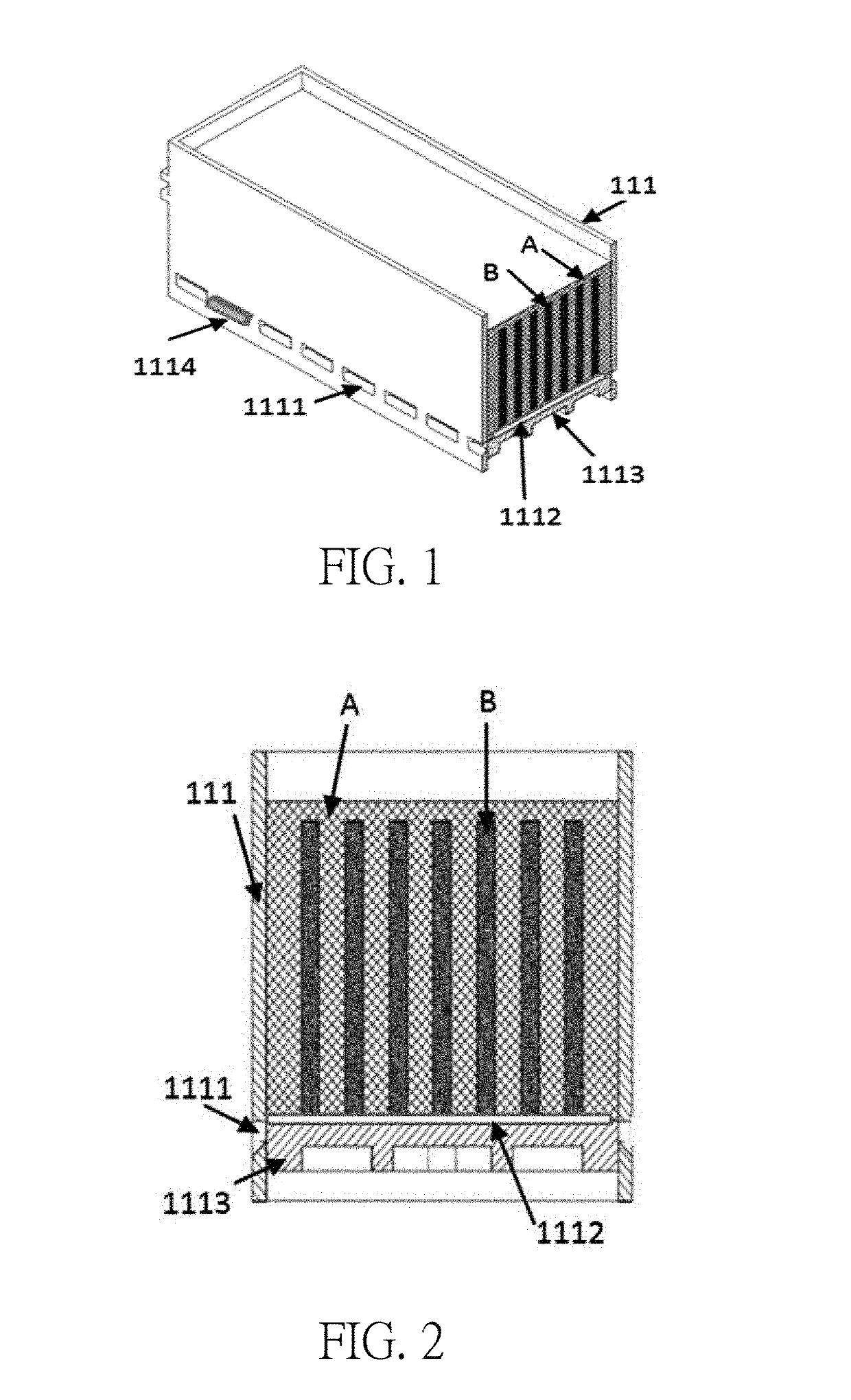
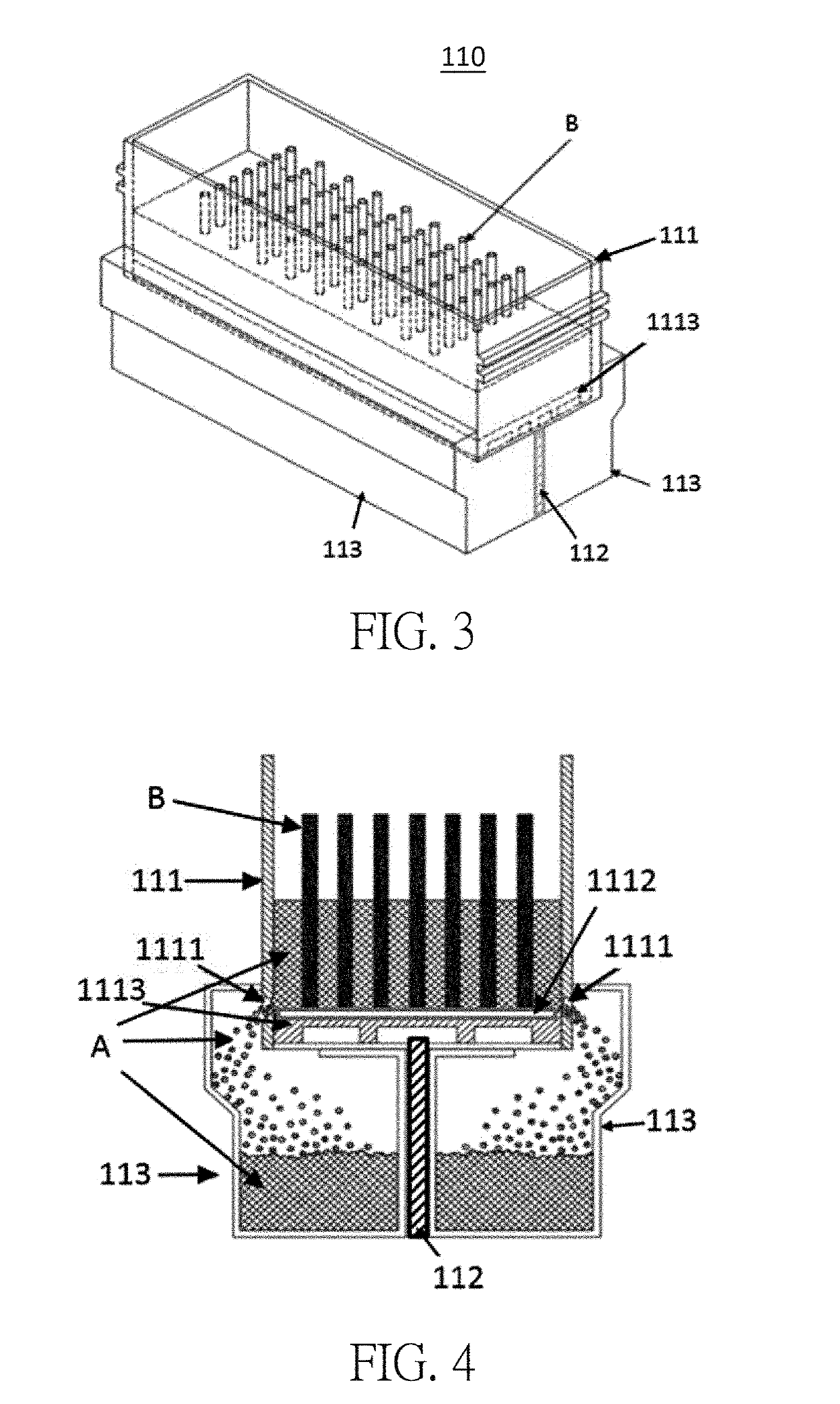
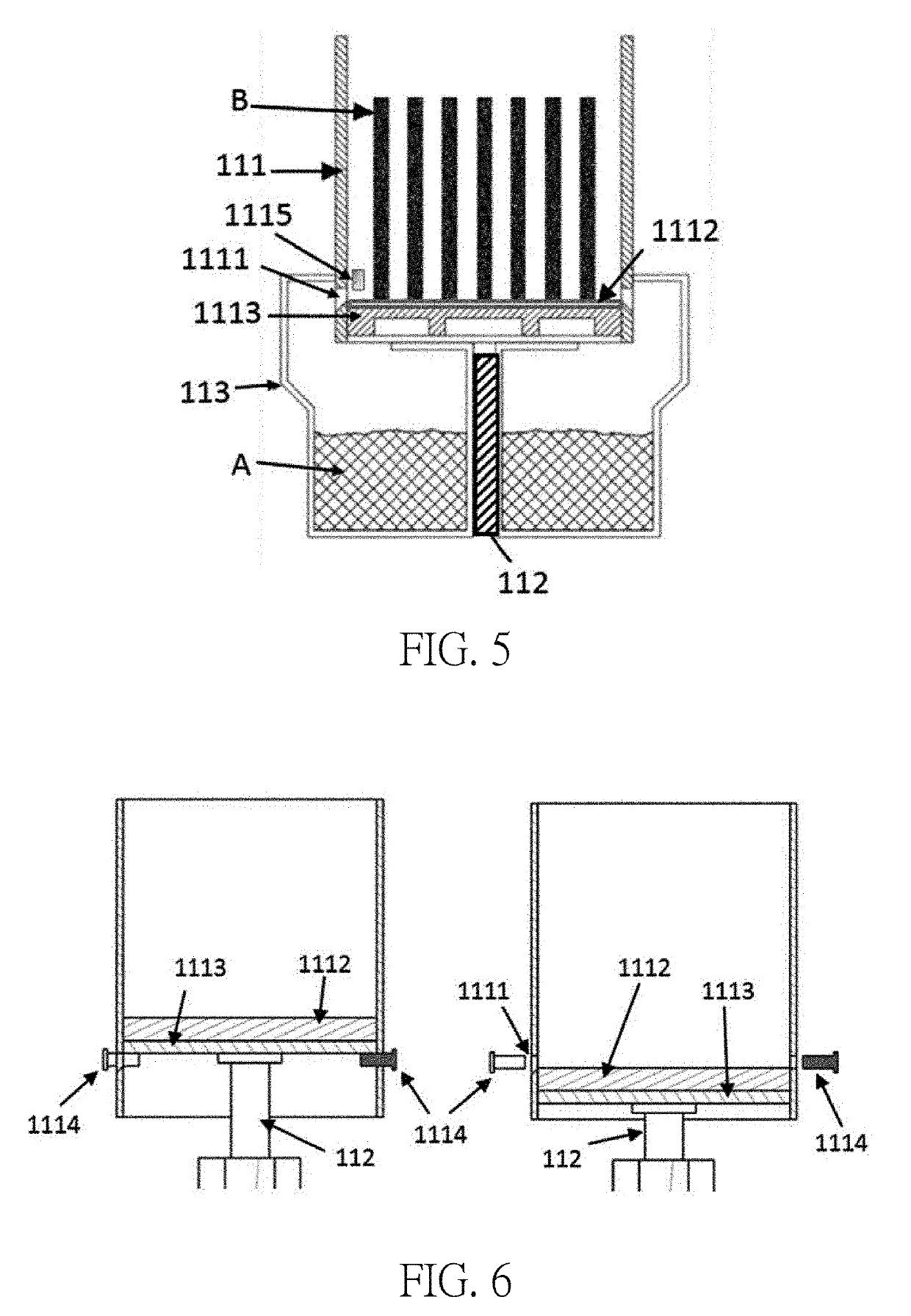
The present application discloses an additive manufacturing chamber, an additive manufacturing module and an additive manufacturing apparatus therewith. Powder discharging openings are formed at a lower portion of the additive manufacturing chamber, and the powders in the additive manufacturing chamber are discharged down via gravitation. The present application further includes a vibrational unit for vibrating the powders so as to accelerate downward powder discharging via vibration of the vibrational unit. The additive manufacturing apparatus can include a main system and a cleaning transportation system separated from the main system. The present application solves the conventional problems of excessive consumed energy, large required installation and operational space, inconvenience of powder removing and swirled raised powder haze in the environment.

Description

BACKGROUND OF THE INVENTION1. Field of the Invention[0001]The invention relates to an additive manufacturing application, and more particularly, to an additive manufacturing chamber with convenience of removing remainder powders in the additive manufacturing chamber and to an additive manufacturing module and an additive manufacturing apparatus therewith.2. Description of the Prior Art[0002]Concerning cleaning an additively manufactured work-piece buried in unprocessed powders filling an additive manufacturing chamber for the additive manufacturing after the additive manufacturing process is finished, one of the conventional methods is to lift and expose the work-piece and a manufacturing platform, whereon the work-piece is shaped and disposed, out from the additive manufacturing chamber so as to collapse the accumulated chunk of powders once exposed, before utilizing a vacuum cleaner or a brush to manually remove the remainder powders on and surrounding the work-piece.[0003]Another...

Claims


Application Information

Patent Timeline
Patent Type & Authority Applications(United States)
IPC IPC(8): B29C64/35B29C64/393B29C64/153B29C64/371B33Y30/00B33Y40/00B33Y50/02
CPCB29C64/35B29C64/393B29C64/153B29C64/371B33Y30/00B33Y40/00B33Y50/02B22F2999/00B29C64/357B29C64/245B29C64/25Y02P10/25B22F10/73B22F10/28B22F12/86B33Y40/20B22F2201/01
Inventor HUANG, CHUNG-CHUNCHEN, CHIH-PENGLIN, PO-SHENTSENG, YU-CHING
Owner NAT CHUNG SHAN INST SCI & TECH
Learn More