Fixed pattern noise mitigation for a thermal imaging system

a thermal imaging system and fixed pattern technology, applied in image enhancement, image analysis, instruments, etc., can solve the problems of limiting the use of high-performance, long-wave imaging to high-value instruments, such as aerospace, military, or large-scale commercial applications, and the cost of thermal imaging sensors has been long, and achieves the effect of reducing fixed pattern noise (fpn) of acquired image data, reducing fpn, and reducing fpn

Active Publication Date: 2019-05-02
SEEK THERMAL
View PDF0 Cites 4 Cited by
  • Summary
  • Abstract
  • Description
  • Claims
  • Application Information

AI Technical Summary

Benefits of technology

[0005]In some embodiments, an imaging system whose Field of View FOV experiences occasional motion in relation to viewed scenes may be configured to reduce Fixed Pattern Noise (FPN) of acquired image data. FPN may be reduced by developing a pixel by pixel FPN correction term through a series of steps including blurring the image, identifying pixels to exclude from some calculations, a motion detector and an FPN updater for frames under motion and an FPN decay element for frames that are still.
[0006]In a first aspect, a method is described for reducing Fixed Pattern Noise (FPN) in an imaging system including at least one imaging sensor and associated image signal processing chain, wherein successive frames of image pixel data are generated and passed to the image processing chain, and where the Field of View (FOV) of the imaging system is subject to occasional motion relative to imaged scenes. The method includes selecting a group of pixels Px,y sig, the group of pixels Px,y sig comprising at least a portion of an image frame, applying an FPN filter to generate an FPN correction term FPNXx,y, and modifying individual pixels of Px,y sig based at least in part on FPNXx,y from a previous image frame to generate a corrected set of pixels Px,y for calculating a value of FPNXx,y for the current frame. Applying the FPN filter includes blurring at least some of the pixels of Px,y to create a blurred pixel set Kx,y and saving the blurred pixel set Kx,y for at least one following frame, wherein Kxy values are available for the current frame and at least one previous frame during the application of the FPN filter; identifying pixels that meet one or more predetermined criteria as excluded pixels for a current image frame; detecting image motion by comparing Kx,y values from the current frame and the at least one previous frame; calculating, when motion is detected, an updated FPNXx,y term based at least in part on Px,y and Kx,y, for current non-excluded pixels and based at least in part on previous FPNXx,y information for currently excluded pixels; and when motion is not detected, decaying FPNXx,y for both excluded and non-excluded pixels.

Problems solved by technology

Such thermal imaging sensors have long been expensive and difficult to produce, thus limiting the employment of high-performance, long-wave imaging to high-value instruments, such as aerospace, military, or large-scale commercial applications.

Method used


Image

  • Fixed pattern noise mitigation for a thermal imaging system
  • Fixed pattern noise mitigation for a thermal imaging system
  • Fixed pattern noise mitigation for a thermal imaging system

Examples


example imaging

Systems

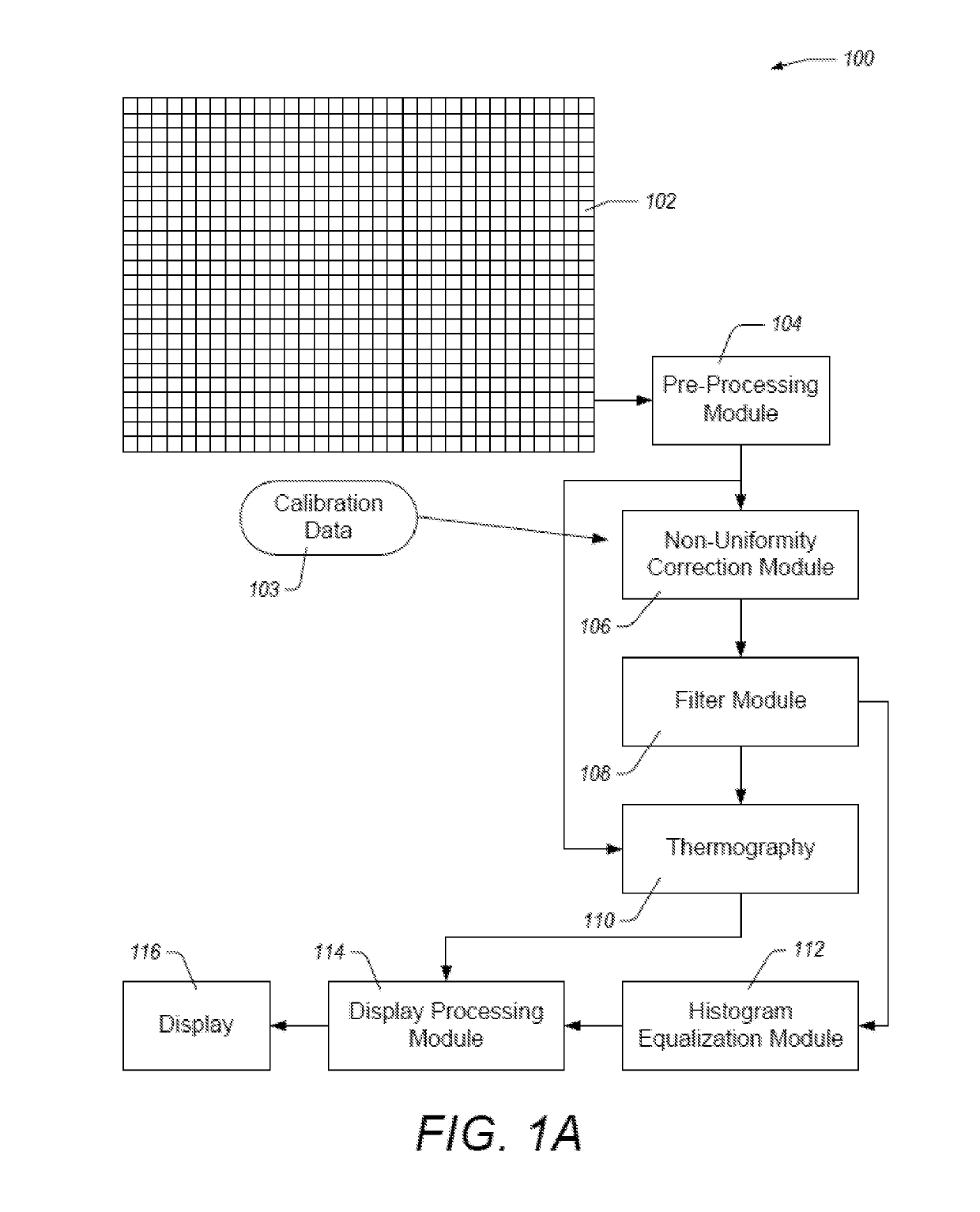
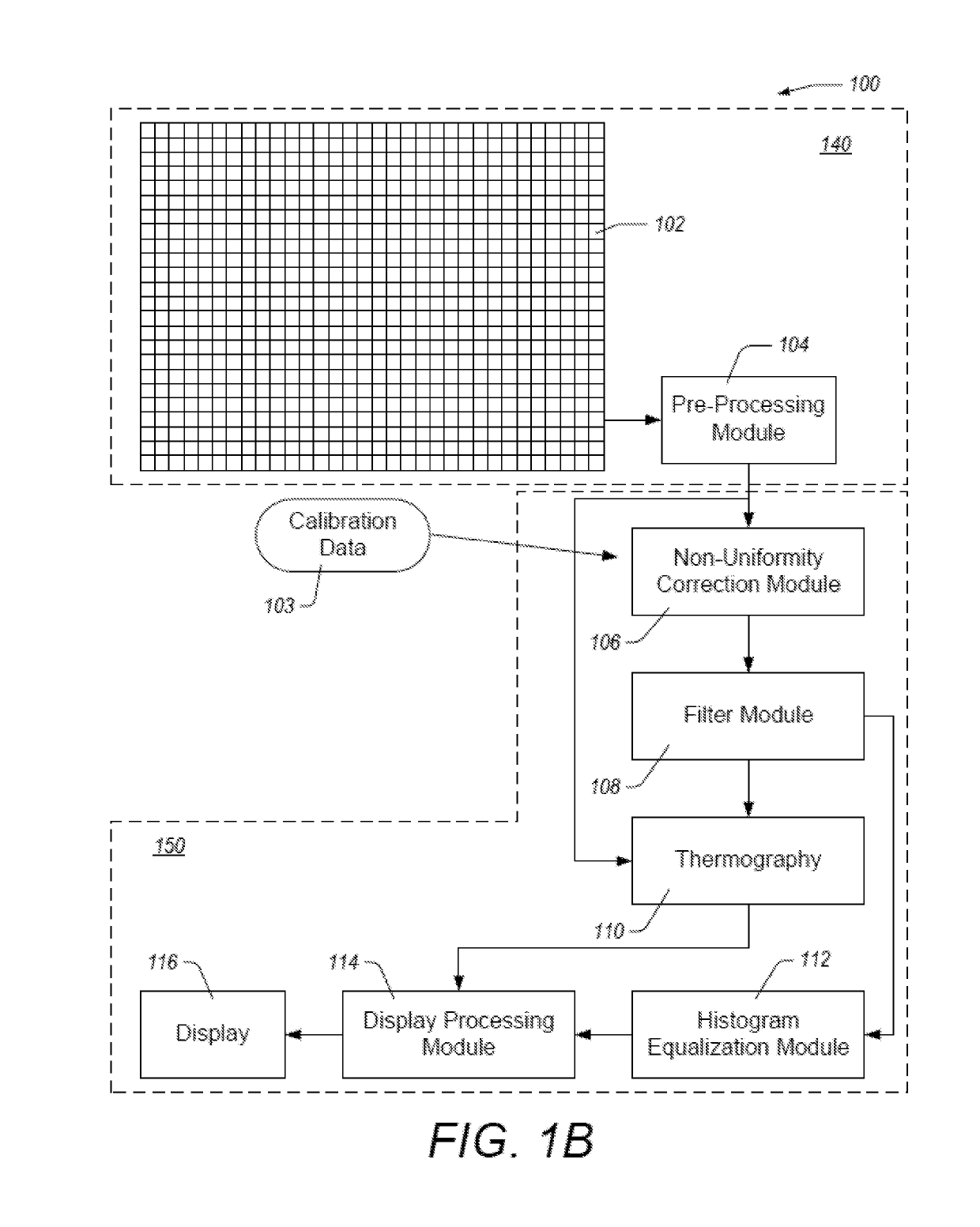
[0046]FIG. 1A illustrates a functional block diagram of an example thermal imaging system 100 comprising an image sensor such as a focal plane array 102, a pre-processing module 104, a non-uniformity correction module 106, a filter module 108, a thermography module 110, a histogram equalization module 112, a display processing module 114, and a display 116. The focal plane array 102 can output a sequence of frames of intensity data (e.g., images, thermal images, etc.). Each frame can include an array of pixel values, each pixel value representing light intensity detected by a corresponding pixel on the focal plane array 102. The pixel values can be read out of the focal plane array 102 as a stream of serial digital data. In some embodiments, the pixel values are read out of the focal plane array 102 using read out electronics that process whole rows or whole columns of the focal plane array 102. In some embodiments, the read out electronics outputs the data as a stream of a f...

example method

for FPN Mitigation

[0085]FIG. 14 illustrates a flow chart of an example method 1400 for mitigating Fixed Pattern Noise. The method 1400 can be implemented using one or more hardware components in an imaging system or image processing system. For ease of description, the method 1400 will be described as being performed by the imaging system 100 described herein with reference to FIGS. 1A and 1B as well as FIGS. 4 and 5. However, one or more of the steps of the method 1400 can be performed by any module or combination of modules in the imaging system 100. Similarly, any individual step can be performed by a combination of modules not shown in the imaging system 100.

[0086]In block 1405, a group of pixels, Px,y sig is selected. The group of pixels Px,y sig may include all or part an image frame. Px,y sig is corrected for FPN using an FPN correction term FPN derived from an FPN filter. For example, it may be advantageous to exclude pixels at or near the image boundaries from the FPN opera...


PUM


Abstract

An imaging system whose Field of View FOV experiences occasional motion in relation to viewed scenes may be configured to reduce Fixed Pattern Noise (FPN) of acquired image data. FPN may be reduced by developing a pixel by pixel FPN correction term through a series of steps including blurring the image, identifying pixels to exclude from some calculations, a motion detector and an FPN updater for frames under motion and an FPN decay element for frames that are still.

Description

CROSS-REFERENCE TO RELATED APPLICATIONS[0001]This application is a continuation-in-part of U.S. application Ser. No. 15 / 629,526, filed Jun. 21, 2017, entitled “FIXED PATTERN NOISE MITIGATION FOR A THERMAL IMAGING SYSTEM,” which claims the benefit of U.S. Provisional Application Ser. No. 62 / 355,797, filed Jun. 28, 2016, entitled “FIXED PATTERN NOISE MITIGATION FOR A THERMAL IMAGING SYSTEM,” both of which are hereby incorporated by reference in its entirety and for all purposes.BACKGROUNDField[0002]The present disclosure generally relates to Fixed Pattern Noise (FPN) reduction for imaging systems, such as cameras including in particular thermal imaging as well as visible imaging cameras, and in particular to systems and methods for developing an FPN filter that can be applied to image data.Description of Related Art[0003]The increasing availability of high-performance, low-cost uncooled infrared imaging devices, such as bolometer focal plane arrays (FPAs), is enabling the design and p...

Claims


Application Information

Patent Timeline
Patent Type & Authority Applications(United States)
IPC IPC(8): G06T5/00G06T5/10
CPCG06T5/002G06T5/10G06T5/20G06T2207/10048G06T2207/20032
Inventor WILLIAMS, ROSSPARRISH, WILLIAM J.WOLFE, JASON
Owner SEEK THERMAL
Why Eureka
Try Eureka