
Gas sensor, and method for measuring concentrations of plurality of target components in gas to be measured

a technology of gas sensor and target component, which is applied in the field of gas sensor, can solve the problems of unreacted ammonia discharge into the atmosphere, difficulty in purifying nox in exhaust gas that contains an excessive amount of oxygen instead of a small amount of cosub>2, and inability to detect effective failure diagnosis techniques with respect to doc catalysts, etc., and achieves accurate measurement

Active Publication Date: 2019-05-02
NGK INSULATORS LTD
View PDF0 Cites 10 Cited by
  • Summary
  • Abstract
  • Description
  • Claims
  • Application Information

AI Technical Summary

Benefits of technology

The patent text describes a gas sensor and a method for measuring the concentrations of multiple components in gas. The gas sensor is capable of accurately measuring over a long period of time the concentration of components that are not combusted, such as exhaust gas, in the presence of oxygen. The method uses a selective reduction type catalyst system (SCR system) that purifies NOx without impacting CO2 emissions. However, in order to increase the efficiency of NOx purification, it is necessary to increase the injected amount of urea, which may lead to unreacted ammonia being discharged into the atmosphere. To address this issue, the present invention provides a gas sensor and method that can accurately measure the concentration of non-combusted components, such as exhaust gas, and multiple components that coexist in the presence of oxygen. This allows for better control and management of emissions regulations.

Problems solved by technology

Diesel engines using lean combustion possess a disadvantage in that it is difficult to purify NOx in exhaust gas that contains an excessive amount of oxygen instead of a small amount of CO2 emissions.
However, if the injected amount of urea is increased, unreacted ammonia may be discharged into the atmosphere.
Although failure diagnosis of DPF and SCR catalysts are possible with existing PM sensors and NOx sensors, an effective failure diagnosis technique has not been discovered with respect to DOC catalysts.
Therefore, although the total amount of NO, NO2, and NH3 can be measured, it is not possible to distinguish between these respective components.
Although the oxide semiconductor electrodes described in Japanese Laid-Open Patent Publication No. 2013-068632 and Japanese Laid-Open Patent Publication 2009-243942 are excellent in terms of the selectivity of NO and NO2, on the other hand, since the sensitivity output characteristics with respect to NO and NO2 are opposite in polarity, under an atmosphere in which both NO and NO2 coexist, it has not been possible to correctly measure the concentration of NO or NO2.

Method used


Image

  • Gas sensor, and method for measuring concentrations of plurality of target components in gas to be measured
  • Gas sensor, and method for measuring concentrations of plurality of target components in gas to be measured
  • Gas sensor, and method for measuring concentrations of plurality of target components in gas to be measured

Examples


first embodiment

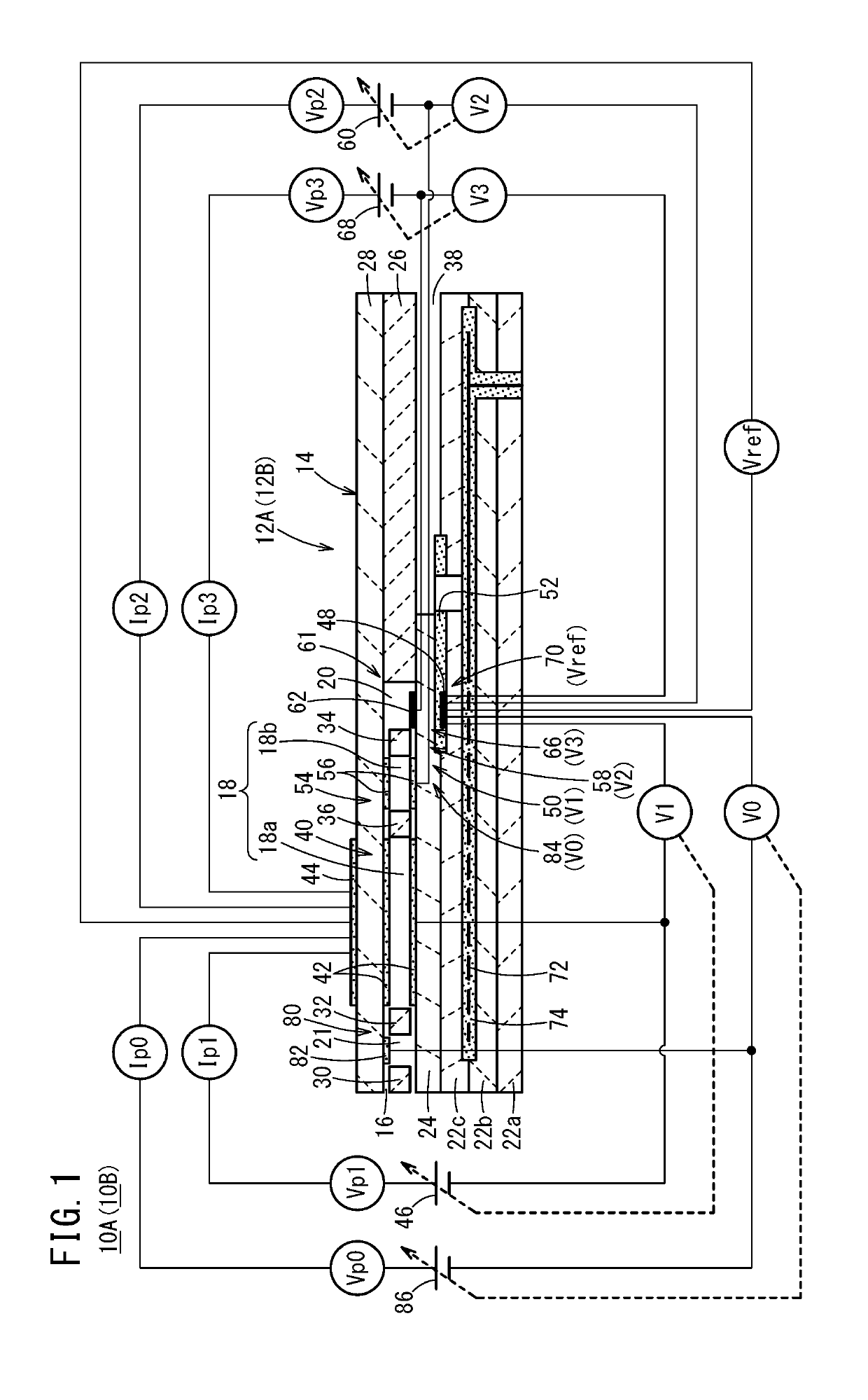
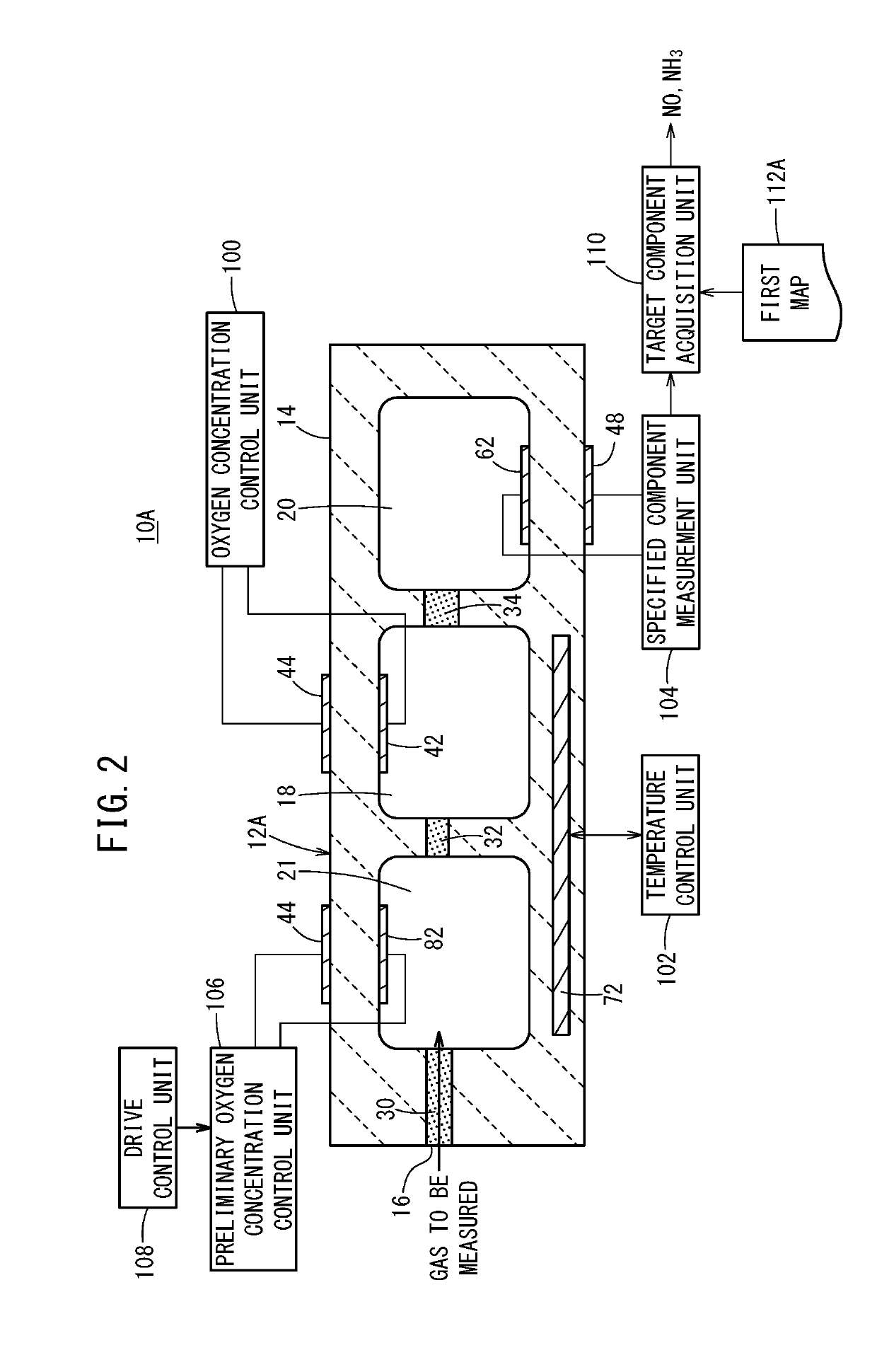
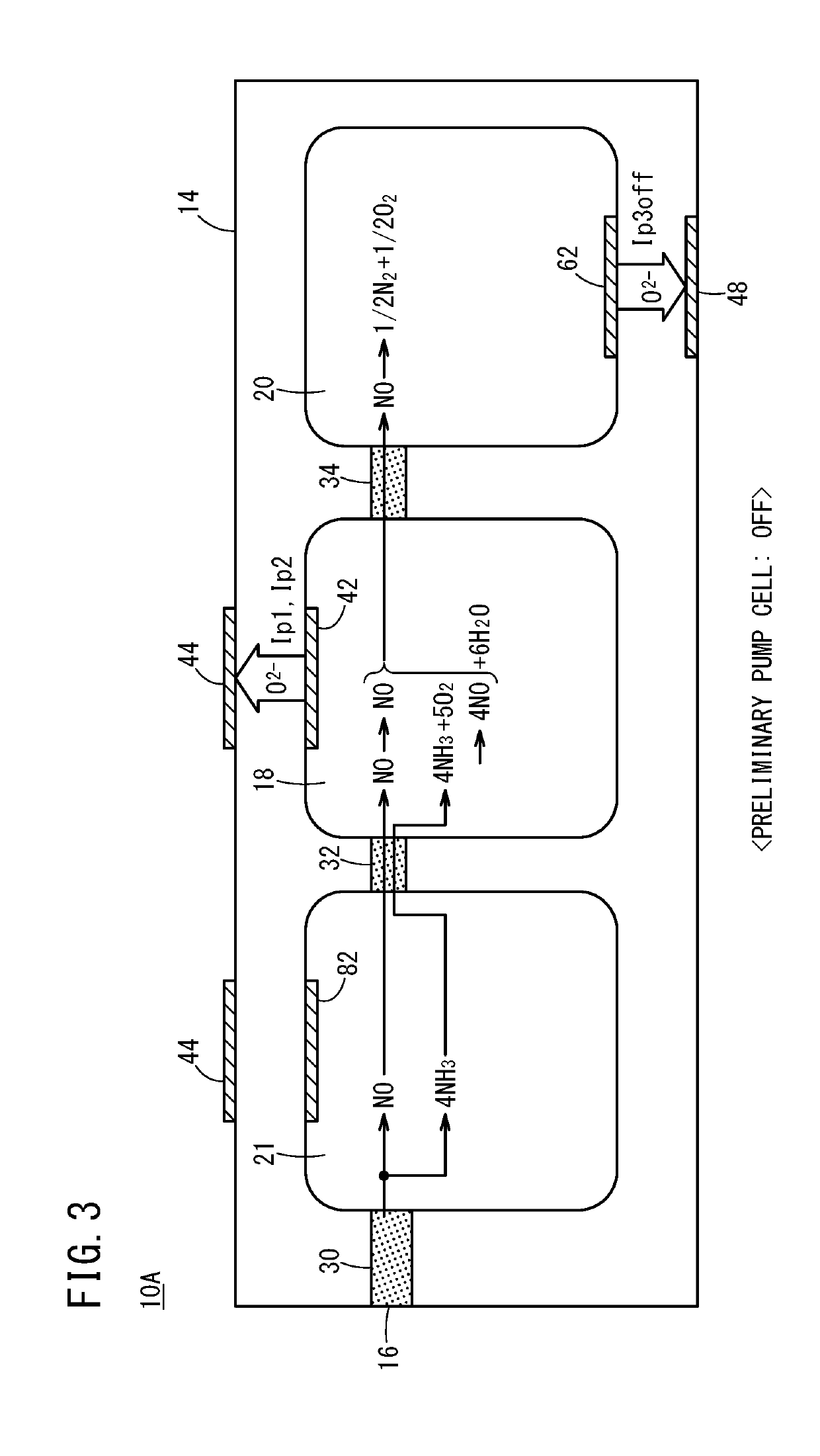
[0058]First, as shown in FIGS. 1 and 2, a gas sensor (hereinafter referred to as a first gas sensor 10A) includes a first sensor element 12A. The first sensor element 12A includes a structural body 14 made up from a solid electrolyte that exhibits at least oxygen ion conductivity, a gas introduction port 16 formed in the structural body 14 and into which a gas to be measured is introduced, an oxygen concentration adjustment chamber 18 formed in the structural body 14 and communicating with the gas introduction port 16, and a measurement chamber 20 formed in the structural body 14 and communicating with the oxygen concentration adjustment chamber 18.

[0059]The oxygen concentration adjustment chamber 18 includes a main adjustment chamber 18a communicating with the gas introduction port 16, and an auxiliary adjustment chamber 18b communicating with the main adjustment chamber 18a. The measurement chamber 20 communicates with the auxiliary adjustment chamber 18b.

[0060]Furthermore, the ...

second embodiment

[0134]Next, a gas sensor (hereinafter referred to as a second gas sensor 10B) will be described further with reference to FIGS. 8 to 13.

[0135]As shown in FIG. 8, the second gas sensor 10B is equipped with a second sensor element 12B having the same configuration as that of the first sensor element 12A of the first gas sensor 10A, however, differs therefrom in that the second target component is NO2.

[0136]Accordingly, by the oxygen concentration control unit 100 or the temperature control unit 102, or alternatively, by the oxygen concentration control unit 100 and the temperature control unit 102, the second gas sensor 10B performs a control so as to convert all of the NO2 into NO, without causing decomposition of NO inside the oxygen concentration adjustment chamber 18.

[0137]On the basis of the preset oxygen concentration condition, and the preliminary electromotive force V0 generated in the preliminary oxygen partial pressure detecting sensor cell 84 (see FIG. 1), the preliminary ...


PUM


Abstract

A gas sensor, and a method for measuring the concentrations of a plurality of target components in a gas to be measured are disclosed. The gas sensor is provided with: a specific component measurement means which measures the concentration of a specific component in a measurement chamber; a preliminary oxygen concentration control means which controls the oxygen concentration in a preliminary adjustment chamber; a drive control means which controls the driving and stopping of the preliminary oxygen concentration control means; and a target component acquisition means which, on the basis of the difference between sensor outputs from the specific component measurement means when the preliminary oxygen concentration control means is being driven and when the preliminary oxygen concentration control means is stopped, and one of the respective sensor outputs, acquires the concentrations of a first target component and a second target component.

Description

CROSS-REFERENCE TO RELATED APPLICATIONS[0001]This application is a Continuation of International Application No. PCT / JP2017 / 022946 filed on Jun. 22, 2017, which is based upon and claims the benefit of priority from Japanese Patent Application No. 2016-124414 filed on Jun. 23, 2016, the contents all of which are incorporated herein by reference.TECHNICAL FIELD[0002]The present invention relates to a gas sensor, which is capable of measuring respective concentrations of a plurality of target components in a gas to be measured, as well as to a method of measuring concentrations of a plurality of target components in a gas to be measured.BACKGROUND ART[0003]Conventionally, an NOx sensor (a serially arranged two-chamber type NOx sensor) having a serially arranged two-chamber structure, and a NOx measurement method using the same (for example, refer to Japanese Laid-Open Patent Publication No. 2015-200643), and a mixed potential type, or a variable resistance type NO2 sensor in which an o...

Claims


Application Information

Patent Timeline
IPC IPC(8): G01N27/409F01N3/20F01N11/00G01N27/41
CPCG01N27/409F01N3/208F01N11/007G01N27/41F01N2560/026F01N2560/021F01N2610/02F01N2610/144G01N27/419G01N33/0037G01N33/0054Y02A50/20
Inventor NAKAGAKI, KUNIHIKO
Owner NGK INSULATORS LTD
Learn More