Additive manufacturing system

a manufacturing system and additive technology, applied in the direction of additive manufacturing, manufacturing tools, additive manufacturing, etc., can solve the problems of serious health impairment, high powder handling risk, and defect in manufactured components, and achieve the effect of simple and inexpensive powder handling system

Inactive Publication Date: 2019-05-02
SIEMENS ENERGY GLOBAL GMBH & CO KG
View PDF0 Cites 11 Cited by
  • Summary
  • Abstract
  • Description
  • Claims
  • Application Information

AI Technical Summary

Benefits of technology

The present invention provides an additive manufacturing system with a hermetically sealable powder handling system. The system includes a movable powder storage container, a stationary powder storage container, and a powder feeding device. The powder handling system is designed to prevent the metallic powder particles from infiltrating the ambient air or deteriorating due to the environment. The system also includes a sieving device for removing oversize material and a vibrator device for emptying the intermediate powder storage container. The stationary powder storage container can be connected to a weighing device for measuring the amount of powder needed for the next build-up process. The powder handling system is simple and inexpensive and prevents health risks and workpiece quality deterioration.

Problems solved by technology

There is currently a high risk for operators handling the powder when operating additive manufacturing systems, in particular when manually filling and emptying its stationary powder storage container.
The fine powder particles infiltrate the ambient air and are breathed in by the operators leading to serious health impairment.
Moreover, the powder itself can be deteriorated or contaminated by the ambient air causing defects in the manufactured components.

Method used


Image

  • Additive manufacturing system
  • Additive manufacturing system
  • Additive manufacturing system

Examples


Embodiment Construction

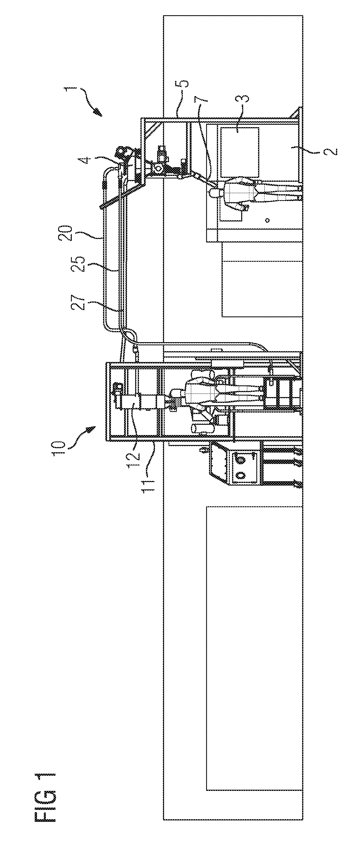
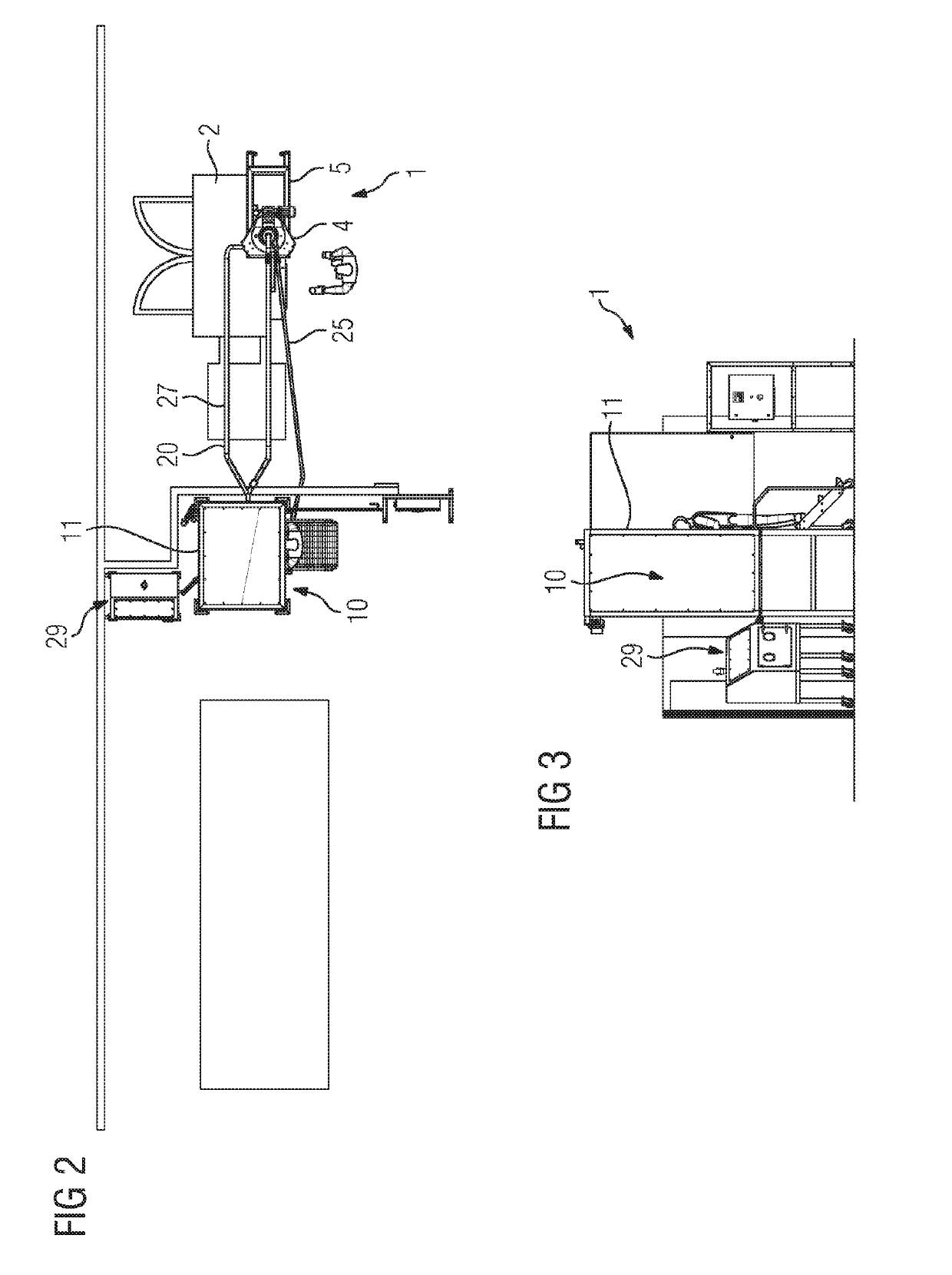
[0030]The drawing shows an additive manufacturing system 1 according to an embodiment of the present invention. The additive manufacturing system 1 comprises a powder based additive manufacturing machine 2, such as for electron beam melting or laser additive manufacturing, having a build chamber 3. In order to supply the build chamber 3 with powder, a stationary powder storage container 4 is positioned above the additive manufacturing machine 2. According to the present embodiment the storage container 4 is fixed to a framework 5 positioned right next to the additive manufacturing machine 2 as shown in detail in FIGS. 6 and 7. However, it is also possible to integrate the storage container 4 in the additive manufacturing machine 2. The storage container 4 is connected to a feeding device 6, which is adapted to batchwise feed powder into the build chamber 3. For this a Y-shaped feeding pipe 7 connects the feeding device 6 with the build chamber 3. The storage container 4 is provided ...


PUM


Abstract

An additive manufacturing system having at least one powder based additive manufacturing machine having a build chamber, at least one stationary powder storage container, and a powder feeding device for feeding powder from the at least one powder storage container into the build chamber. The build chamber, stationary powder storage container and powder feeding device form a part of a powder handling system, which is hermetically sealable in a powder-tight manner and to which a movable powder storage container is connected. The powder handling system selectively feeds powder from the movable powder storage container to the stationary powder storage container or removes powder from the build chamber in the hermetically sealed state. A method for feeding powder into and removing powder from a build chamber of at least one additive manufacturing machine, where the feeding and the removal of the powder takes place within a hermetically sealable powder handling system.

Description

CROSS REFERENCE TO RELATED APPLICATIONS[0001]This application is the US National Stage of International Application No. PCT / EP2017 / 060684 filed May 4, 2017, and claims the benefit thereof. The International Application claims the benefit of European Application No. EP16168715 filed May 9, 2016. All of the applications are incorporated by reference herein in their entirety.FIELD OF INVENTION[0002]The present invention relates to an additive manufacturing system comprising at least one powder based additive manufacturing machine having a build chamber, at least one stationary powder storage container, and a powder feeding device for feeding powder from the at least one powder storage container into the build chamber.BACKGROUND OF INVENTION[0003]Various types of powder based additive manufacturing systems of the above-mentioned kind are already known, such as for electron beam melting or laser additive manufacturing. They all have in common that a workpiece is build up in layers on the...

Claims


Application Information

Patent Timeline
IPC IPC(8): B22F3/00B22F3/105B33Y10/00B33Y30/00B33Y40/00
CPCB22F3/003B22F3/1055B33Y10/00B33Y30/00B33Y40/00B22F2003/1056B29C64/153B29C64/20B29C64/321B29C64/25Y02P10/25B22F10/73B22F12/50B22F12/13B22F12/80B22F12/52B22F10/68B22F10/28B22F10/34Y02P10/20
Inventor GRAICHEN, ANDREASJOHANSSON, PONTUSNORDENBERG, EVAPERSSON, ANDERS
Owner SIEMENS ENERGY GLOBAL GMBH & CO KG
Why Eureka
Try Eureka