Coupling for coupling a vacuum hose to a central vacuum source

A technology for vacuum hoses and connectors, applied in the direction of suction hoses, vacuum cleaners, applications, etc., can solve the problems of complex and expensive manufacturing, and achieve the effect of low-cost structure, the lowest loss of suction, and a simple structure

Inactive Publication Date: 2011-02-09
乔纳斯 哈内
View PDF5 Cites 0 Cited by
  • Summary
  • Abstract
  • Description
  • Claims
  • Application Information

AI Technical Summary

Problems solved by technology

But the structure of the system is

Method used


Image

  • Coupling for coupling a vacuum hose to a central vacuum source
  • Coupling for coupling a vacuum hose to a central vacuum source
  • Coupling for coupling a vacuum hose to a central vacuum source

Examples


Embodiment Construction

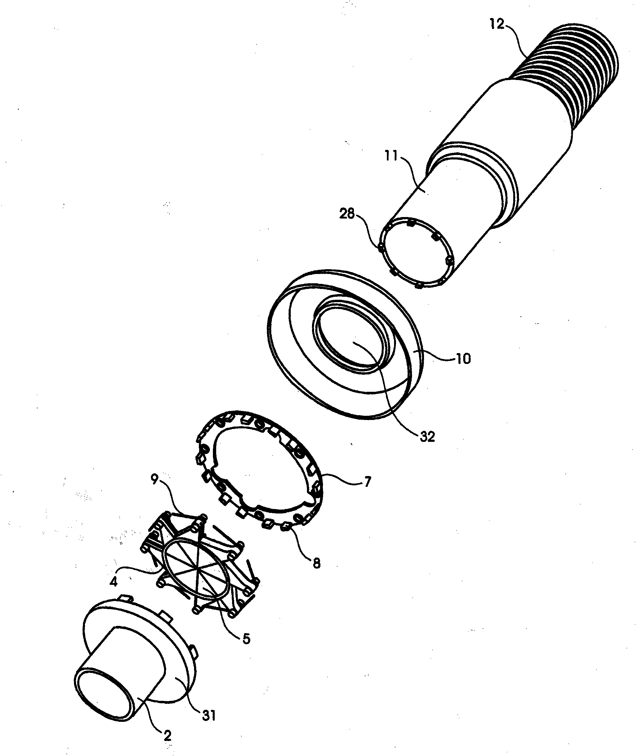
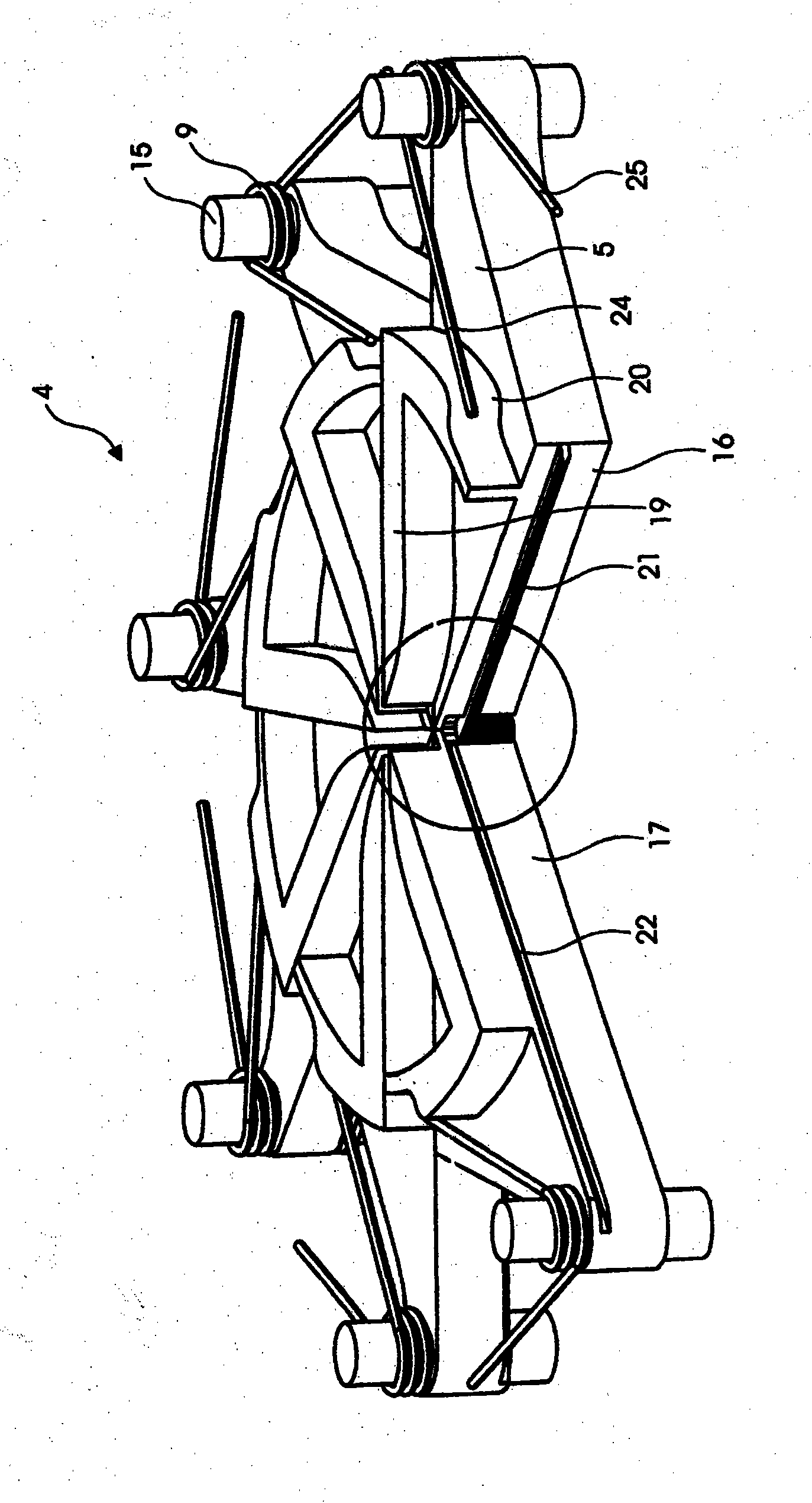
[0043] The connector of the invention shown in the figures is as an example intended for use in connecting a flexible vacuum hose with a nozzle used in a building for vacuum cleaning areas to a central vacuum placed behind a partition in a building such as a wall source. figure 1 Shown in the exploded view, the connector 1 includes: through the partition wall 3 ( figure 1 not shown) an extended tube head 2, in this example a valve 4 with 8 pivotally placed valve parts 5 to open and close a port 6 in the tube head, a seat ring 7 with a seat 8, For restoring the spring 9 ( figure 1 not shown), a cup 10 for covering the valve, and a tubular adapter 11 attached to a flexible vacuum hose 12 and fitted into a port in the tube head.

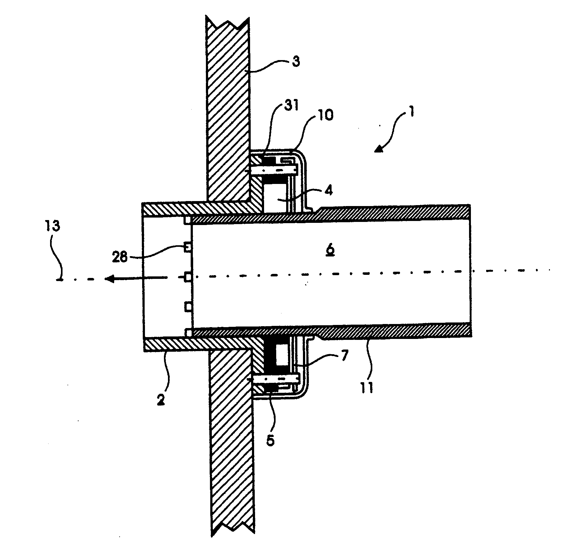
[0044] figure 2 shows an axial cross-section of the connector 1 in the installed state, with the head 2 passing through the partition wall 3 , the valve 4 is opened and the adapter 11 is pressed axially into the port of the head 2 through the openin...


PUM


Abstract

A coupling (1) for coupling a flexible vacuum hose (12) to a central vacuum source placed behind a partition (3) forms an annular port (6) through the partition (3), defining an axis (13), and comprises a valve (4) for opening and closing the port (6), and a tubular adapter (11) of the hose (12) fitting into the port (6). The valve (4) is divided up into a number of valve sections (5), each having an arm (14) for pivotally connecting the valve section (5) to a pivot (15) placed outside the port (6), and an elongated cam (19) for-during opening of the valve (4) -being engaged with a projection (28) which is formed on the adapter (11) and which loads the valve section (5) with a moment in the opening direction by partially turning the adapter (11) into the opposite direction. Using one hand only, the user can readily perform the coupling and decoupling of the flexible vacuum hose (12) to the central vacuum source.

Description

technical field [0001] The invention relates to a connector for connecting a vacuum hose to a central vacuum source placed behind a partition wall, comprising an annular port through the partition wall, the port defining an axis, a valve to open and close the port and a hose fitted to the port Tubular adapter. [0002] The invention also relates to a method of connecting a flexible hose to and disconnecting the connector from a central vacuum source placed behind a partition wall by using the connector of the invention. Background technique [0003] In particular, central vacuum sources are used in large buildings to avoid the tedious and tedious work of transporting heavy vacuum cleaners from one place to be vacuumed to another over long distances and often under difficult conditions. [0004] A central vacuum source advantageously allows the use of a lightweight flexible hose with a nozzle at one end and a tubular adapter at the other end to replace a heavy vacuum cleaner...

Claims


Application Information

Patent Timeline
IPC IPC(8): A47L5/38A47L9/24
CPCF16K3/03A47L5/38A47L9/242
Inventor 乔纳斯·哈内
Owner 乔纳斯 哈内
Why Eureka
Try Eureka