Rotor with a locking plate for securing an antirotation lock against unscrewing

Active Publication Date: 2018-01-25
SIEMENS ENERGY GLOBAL GMBH & CO KG
View PDF2 Cites 1 Cited by
  • Summary
  • Abstract
  • Description
  • Claims
  • Application Information

AI Technical Summary

Benefits of technology

The present invention is for a rotor used in a device. The rotor has a locking ring that is fastened to the rotor disk using an anti-rotation lock. The locking ring securely holds a support ring on the rotor disk, eliminating the need for a separate locking plate. The locking ring has a recess for engaging with a locking plate. The rotor disk has a cutout that aligns with the recess when the locking ring is in position. This design is inexpensive and simple, making it ideal for use in various devices.

Problems solved by technology

Such a frequency shift can involve unacceptably high vibration amplitudes which can impair the function of the rotor and lead to damage.
The use of such a dummy rotor disk, however, is accompanied by high costs, which is not desirable.

Method used


Image

  • Rotor with a locking plate for securing an antirotation lock against unscrewing
  • Rotor with a locking plate for securing an antirotation lock against unscrewing
  • Rotor with a locking plate for securing an antirotation lock against unscrewing

Examples


Embodiment Construction

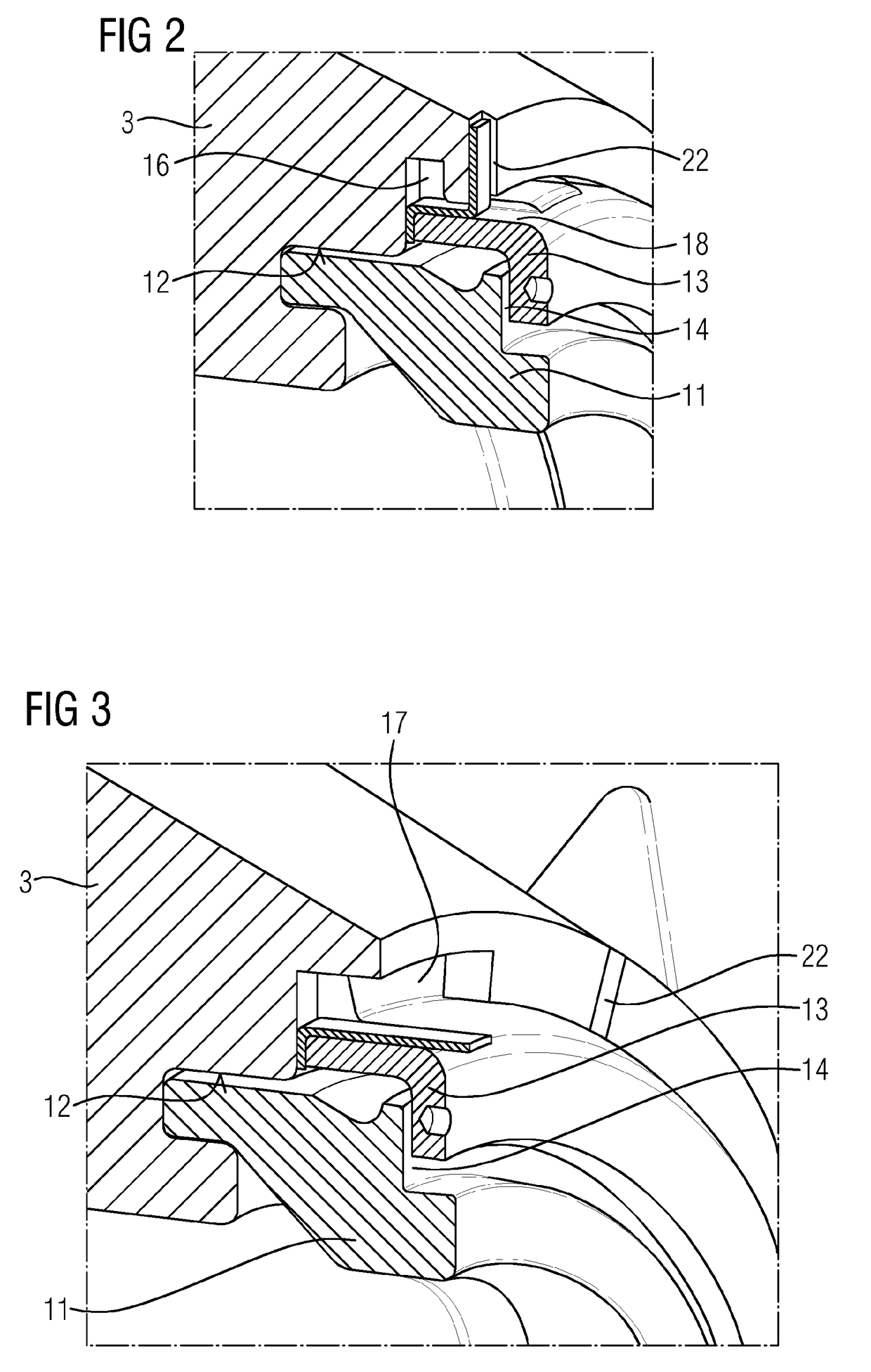
[0027]FIGS. 1 to 7 show a rotor according to an embodiment of the present invention. The rotor 1, which in the present case forms a gas turbine rotor, comprises a multiplicity of rotor disks 3 having in each case an axial through-hole 2, a hollow shaft 4 and a tie rod 5 which extends through the through-hole 2 and through the hollow shaft 4 and via which the rotor disks 3 and the hollow shaft 4 are axially clamped in a known manner using clamping parts 6 which are screwed onto the tie rod 5 at the end. In this case, the rotor disks 3 are assembled to form a compressor-side rotor disk unit 7 and a turbine-side rotor disk unit 8, wherein the hollow shaft 4 is arranged between the two rotor disk units 7 and 8. The end faces, which face each other, of directly adjacently arranged rotor disks 3 are provided in each case with a Hirth toothing, not shown in more detail, as a result of which, as a consequence of the clamping by means of the tie rod, a form-fitting connection between the adj...


PUM


Abstract

A rotor, in particular a gas turbine rotor, having multiple rotor discs, each of which has an axial through-opening, and the rotor discs are axially clamped by at least one tie rod extending through the through-openings and are combined so as to form at least one rotor disc unit. At least one support ring which surrounds the tie rod and is in engagement with a paired rotor disc rests against the outer diameter of the tie rod, and the tie rod is supported against the rotor disc by the support ring. In order to axially secure the at least one support ring, at least one securing ring is provided which is secured to the paired rotor disc by a rotational lock and which holds the support ring against the rotor disc. The securing ring is prevented from unscrewing by a securing plate.

Description

CROSS REFERENCE TO RELATED APPLICATIONS[0001]This application is the US National Stage of International Application No. PCT / EP2016 / 050193 filed Jan. 7, 2016, and claims the benefit thereof. The International Application claims the benefit of European Application No. EP15157557 filed Mar. 4, 2015. All of the applications are incorporated by reference herein in their entirety.FIELD OF INVENTION[0002]The present invention relates to a rotor, especially to a gas turbine rotor, with a plurality of rotor disks having in each case an axial through-hole, which rotor disks, via at least one tie rod extending through the through-holes, are axially clamped and assembled to form at least one rotor disk unit, wherein at least one support ring, encompassing the tie rod, butts against the outside diameter of the tie rod, which support ring engages with an associated rotor disk and is supported on the rotor disk via the tie rod, and wherein for axially securing the at least one support ring provisi...

Claims


Application Information

Patent Timeline
IPC IPC(8): F01D5/06F01D5/08F04D29/26F01D5/30
CPCF01D5/066F01D5/3015F01D5/082F01D5/3069F04D29/266F01D5/087F05D2260/33F05D2260/96F05D2260/30
Inventor KAMPKA, KEVINKOLK, KARSTENSCHRODER, PETERVEITSMAN, VYACHESLAV
Owner SIEMENS ENERGY GLOBAL GMBH & CO KG
Why Eureka
Try Eureka