Eureka AIR delivers breakthrough ideas for toughest innovation challenges, trusted by R&D personnel around the world.

Female Cabling Connector

a female cabling and connector technology, applied in the field of female cabling connectors, can solve the problems of both connectors, current mating connection problems, and continual misalignment of the mating connector, and achieve the effects of wide possible variance in the diameter of male connectors, easy and secure connection, and easy disconnection

Inactive Publication Date: 2019-04-25
SIMMONDS SIMON
View PDF5 Cites 3 Cited by
  • Summary
  • Abstract
  • Description
  • Claims
  • Application Information

AI Technical Summary

Benefits of technology

The device described in this patent provides a solution to problems with damaged connections and misaligned male and female connectors in high power cabling connections. It achieves easy and secure connections despite misalignment, diameter mismatches, and user handling. The female connector is designed to accommodate the inserted male conductor through a wide range of diameters, and includes a torsion spring or a flexible annular body to securely engage with the male conductor. The technical effects of the device involve improved reliability and durability of the electrical connection, reducing the risk of malfunctions and downtime.

Problems solved by technology

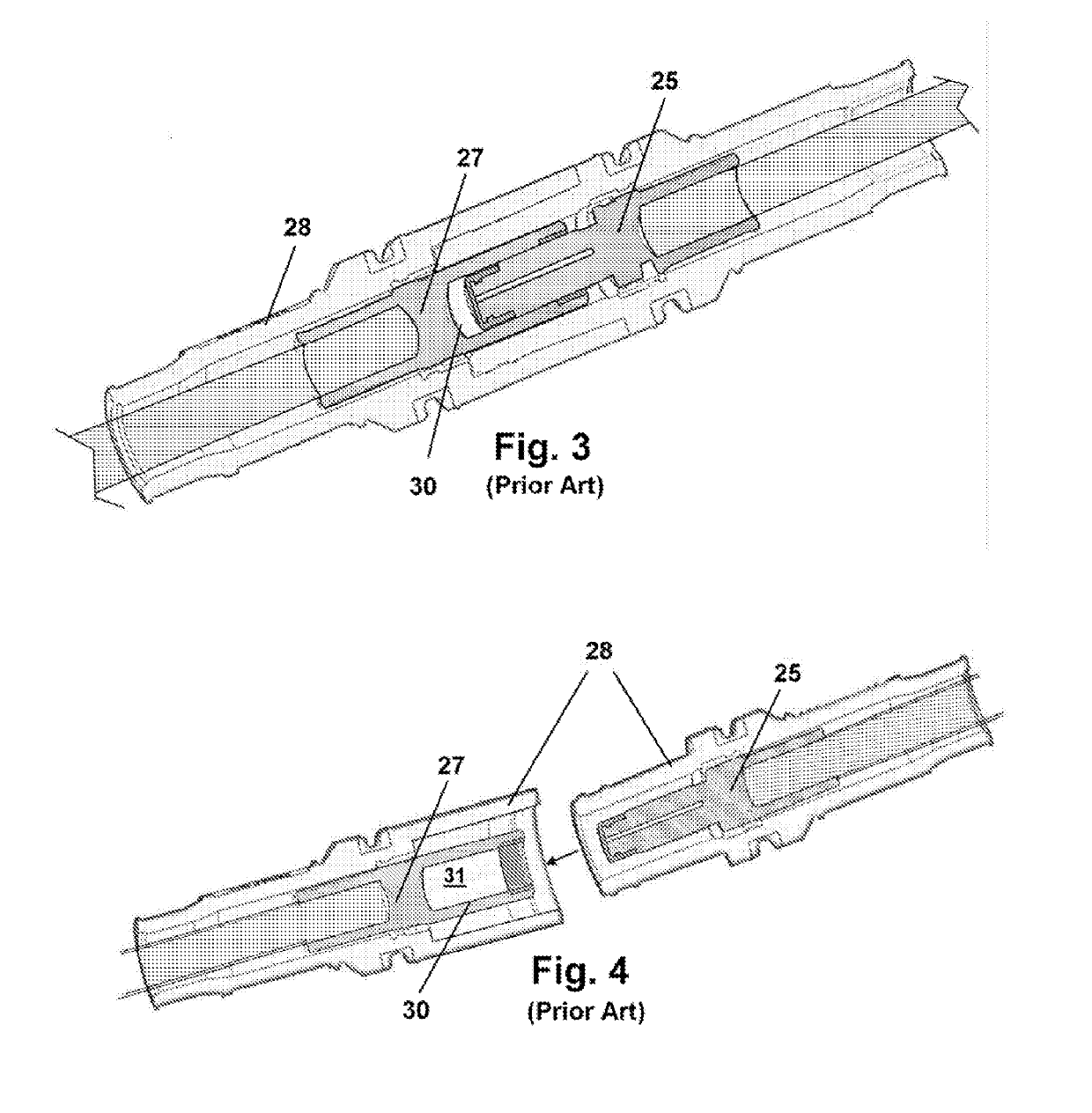
However, while current complimentary connections between male and female fittings of such high power cables has standardized to provide covered and insulated connectors adapted for complimentary engagement of cable ends to receptacles, such mating connections currently suffer from a number of issues relating to problems associated with misalignment of the cables with mating receiving receptacles during engagement thereof.
Such is caused frequently by the fact that the male connectors and female receptors are covered by insulation rendering the internally housed conductors out of view during engagement between the male fitting to the female or mating receptacle.
The heavy cable and awkward elevated or lowered positioning compounded by the lack of the ability to view and align the insulated conductors, causes continual misalignments of the mating connectors during use.
Additional problems are caused by the nature of the adjustability of the diameter of the male connectors which frequently will have been adjusted to a diameter exceeding the female connector to which it is to be engaged.
As a consequence, workers having to deal with stubborn connectors, which will not properly mate due to oversized cable connectors and misalignments of the mating connectors, have a tendency to force the engagement between the male and female connectors using brute force, hammers, and other manners of forcing the male and female conductors into a cooperative power-communicating engagement.
As can be discerned, because the male and female conductors forming the connections for these engagements are conventionally formed of copper, the forcing of mis-aligned connectors together, such as by pounding, can cause physical damage to both connectors, and cause what is known as a “cold weld” between the male and female connections due to their being forced together while out of alignment.
This can damage both the male and female connectors to the point they cannot be separated, or if they are separated using significant force, the are rendered useless for subsequent engagements, unless the users wish to damage an additional pair of connectors.
Various limitations of the related art will become apparent to those skilled in the art upon a reading and understanding of the specification below and the accompanying drawings.

Method used


Image

  • Female Cabling Connector
  • Female Cabling Connector
  • Female Cabling Connector

Examples


Embodiment Construction

[0030]In this description, the directional prepositions of up, upwardly, down, downwardly, front, back, top, upper, bottom, lower, left, right and other such terms refer to the device as it is oriented and appears in the drawings and are used for convenience only; they are not intended to be limiting or to imply that the device has to be used or positioned in any particular orientation.

[0031]Now referring to drawings in FIGS. 1-11, wherein similar components are identified by like reference numerals, there can be seen in FIG. 1, an isometric view of a mode of the device 10 herein, having an annular body 15 as described herein in various modes, positioned in an as-used or operative positioning within the receiving cavity 30, for a female receptacle adapted for circumferential engagement around a male connector for high amperage electric equipment.

[0032]The depicted annular body 15 of FIG. 1 and FIG. 2, is formed in a preferred shape formed by the shaped wires 11, of a hyperbolic cyli...


PUM


Abstract

An electric receptacle adapted for insertion and electric engagement of a cylindrical male electric connector is provided. The receptacle employs an annular body defining an axial receiving cavity for the male connector. An angled annular polymeric insert at a leading edge may provide a guide into the receiving cavity which is preferably shaped to form a hyperbolic cylindrical grid structure from a plurality of shaped wires running in parallel paths.

Description

[0001]This application claims priority to U.S. Provisional Application Ser. No. 62 / 249,678 filed on Nov. 2, 2015, which is included herein in its entirety by this reference thereto.BACKGROUND OF THE INVENTION1. Field of the Invention[0002]The present invention relates generally to connectors for employment in the communication of power in electrical systems carrying high amperage electricity such as Substation Modernization Platform cabling. More particularly, the invention relates to an improved female receptacle or receiving connector configured for a surrounding frictional engagement with a male connector in high amperage electric connections.2. Prior Art[0003]Single-pole cable connections positioned at the terminating ends of electric cables employed to communicate high amperage electrical power requirements are used in a variety of industrial settings, such as oil and other drilling platforms, stage power requirements at concerts, and other electric equipment requiring high pow...

Claims


Application Information

Patent Timeline
Patent Type & Authority Applications(United States)
IPC IPC(8): H01R13/187H01R13/11H01R13/33
CPCH01R13/187H01R13/111H01R13/33
Inventor SIMMONDS, SIMON
Owner SIMMONDS SIMON
Why Eureka
Eureka Blog
Learn More