
Method for operating an internal combustion engine and electronic control unit for an internal combustion engine

a technology of electronic control unit and internal combustion engine, which is applied in the direction of electric control, fuel injection control, machines/engines, etc., can solve the problems of complex control of internal combustion engine fuel injection into the combustion chamber of the cylinder, impair the precision of the determination of these features, etc., and achieves the correction of the frequency-transformed pressure spectrum. , the effect of improving the precision of the method

Active Publication Date: 2019-03-28
ROBERT BOSCH GMBH
View PDF0 Cites 5 Cited by
  • Summary
  • Abstract
  • Description
  • Claims
  • Application Information

AI Technical Summary

Benefits of technology

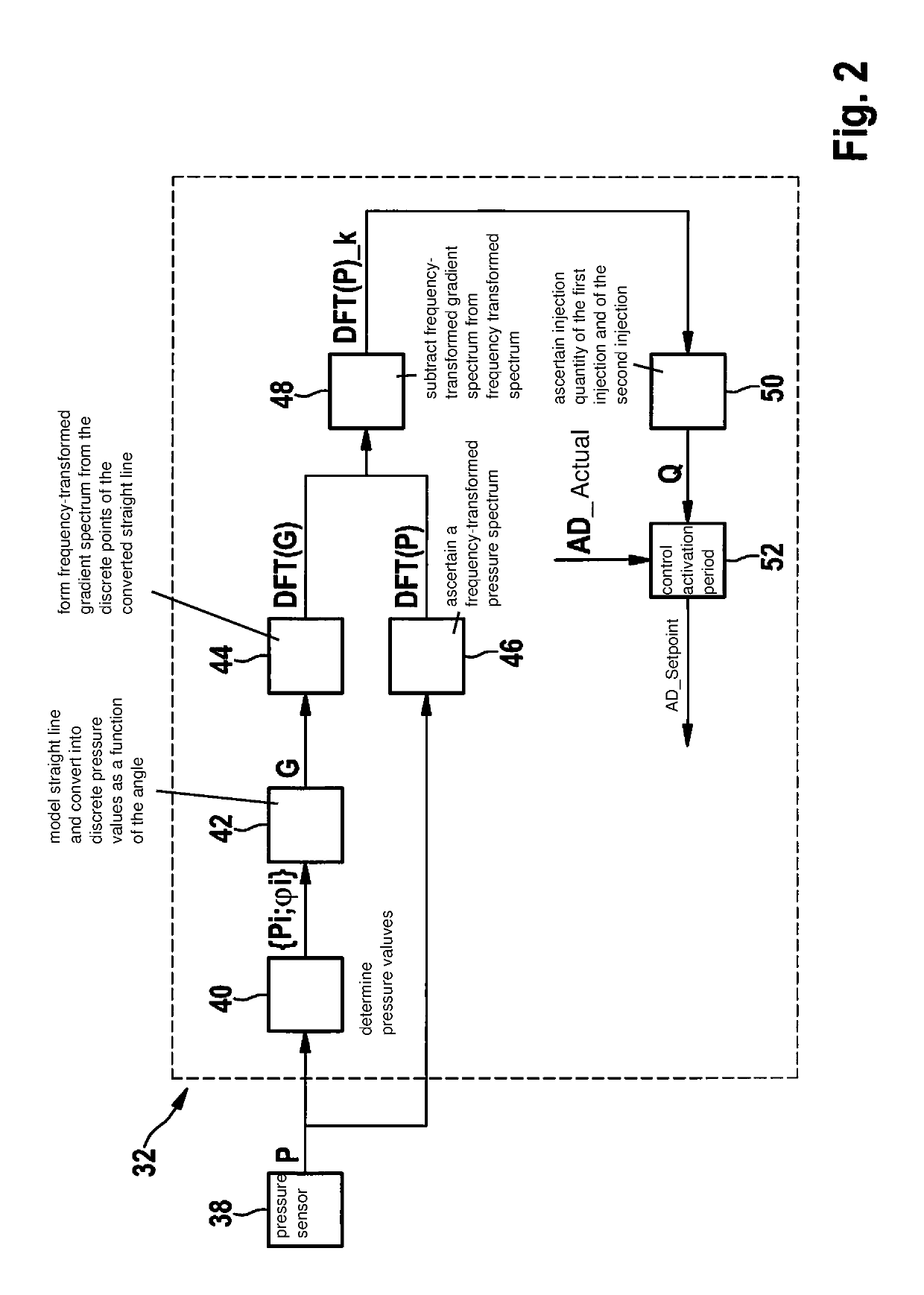
The present invention provides a method for accurately compensating for pressure gradients in an engine controller. This method requires minimal computing steps and is easy to implement. The method includes a simple model to estimate the pressure gradient and compensates for it by making a difference between the pressure spectrum and the gradient spectrum. The method also takes into account fluctuations in pressure conditions over the course of multiple injections, which improves the precision of the method. Overall, this method allows for accurate and precise injection control in an engine controller.

Problems solved by technology

Controlling an injection of fuel into a combustion chamber of a cylinder of an internal combustion engine is a complex task.
The selection of the evaluation windows may represent a minor computing effort when implementing the method.
It is noted that in all methods that work in the frequency space, i.e., which are able to use the amplitude or phase position of a frequency-transformed function or of frequency-transformed measured values as a feature, such gradients may impair a precision of the determination of these features.

Method used


Image

  • Method for operating an internal combustion engine and electronic control unit for an internal combustion engine
  • Method for operating an internal combustion engine and electronic control unit for an internal combustion engine
  • Method for operating an internal combustion engine and electronic control unit for an internal combustion engine

Examples


Embodiment Construction

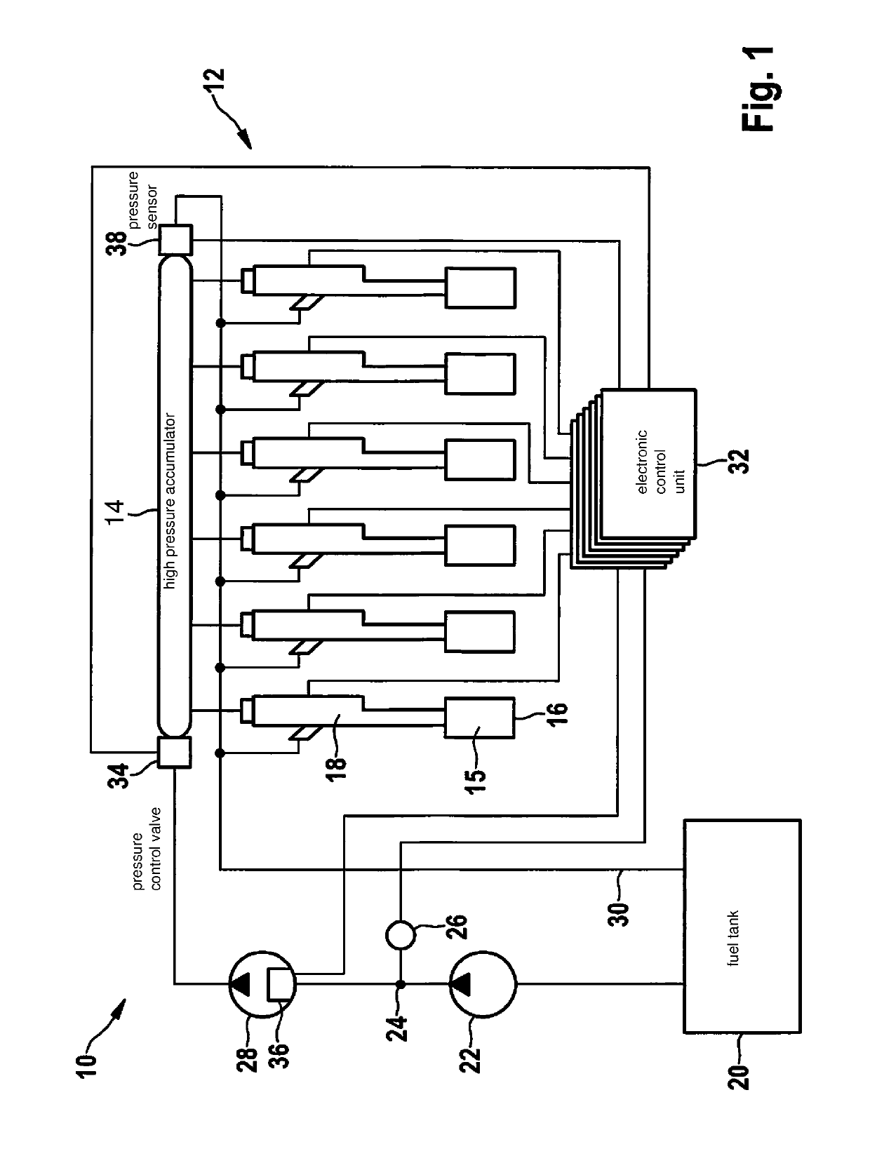
[0030]A six-cylinder internal combustion engine 10 of a diesel motor vehicle includes a fuel injection 12 which is designed as a common-rail system. Fuel injection 12 is configured to withdraw fuel in the form of diesel from a high-pressure accumulator 14 of fuel injection 12 and to inject same into a combustion chamber 15 of cylinders 16 of internal combustion engine 10 with the aid of assigned injectors 18. For the sake of clarity, only one combustion chamber 15, one cylinder 16, and one injector 18 are provided with a reference numeral.

[0031]Fuel injection 12 includes a fuel tank 20 which is connected downstream from a fuel delivery pump 22, which is designed as a low-pressure pump, via a corresponding supply line 24. Fuel delivery pump 22 is connected via a pressure control valve 26 in feed line 24 to a high-pressure pump 28 which, in turn, is in fluid connection with high-pressure accumulator 14. The fuel is feedable from high-pressure accumulator 14 to identically designed inj...


PUM


Abstract

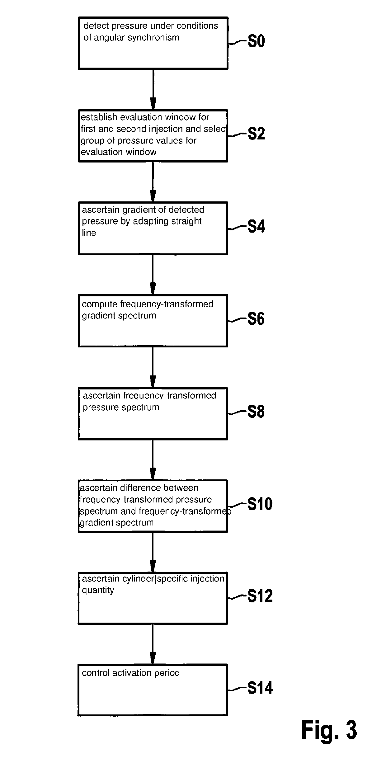
A method for operating an internal combustion engine is provided in which fuel is withdrawn from a high-pressure accumulator and injected into a combustion chamber of at least one cylinder of the internal combustion engine, the method including the steps of detecting under conditions of angular synchronism a pressure of the fuel in the high-pressure accumulator during a first injection into the at least one cylinder and during a later, second injection into the at least one cylinder; ascertaining a gradient of the detected pressure; ascertaining a frequency-transformed spectrum of the detected pressure and a frequency-transformed spectrum of the ascertained gradient; correcting the frequency-transformed spectrum of the detected pressure by the frequency-transformed spectrum of the ascertained gradient; and ascertaining a cylinder-individual injection quantity of fuel, which was injected into the at least one cylinder, from the corrected frequency-transformed spectrum of the detected pressure.

Description

CROSS REFERENCE[0001]The present application claims the benefit under 35 U.S.C. § 119 of German Patent Application No. DE 102017217113.8 filed on Sep. 26, 2017, which is expressly incorporated herein by reference in its entirety.FIELD[0002]The present invention relates to a method for operating an internal combustion engine, an electronic control unit for an internal combustion engine, a computer program as well as a machine-readable memory medium.BACKGROUND INFORMATION[0003]Controlling an injection of fuel into a combustion chamber of a cylinder of an internal combustion engine is a complex task. For example, a point of injection and an injection quantity of the fuel to be injected must be precisely determined. These two parameters may, however, change during an operation of the internal combustion engine, for example as a function of an operating point, and / or over a service life of the internal combustion engine.[0004]A method is described in German Patent No. DE 10 2014 215 618 ...

Claims


Application Information

Patent Timeline
Patent Type & Authority Applications(United States)
IPC IPC(8): F02D41/40F02D41/00F02D41/26F02D41/38F02D41/14
CPCF02D41/402F02D41/008F02D41/26F02D41/3827F02D41/1401F02D2041/1433F02D2041/389F02D2041/1429F02D41/38F02D41/3836F02D2041/288F02D2200/0602F02D2250/14
Inventor REILING, FLORIANHONDROS, CHRISTOS
Owner ROBERT BOSCH GMBH
Learn More