
Assessment of Wound Status and Tissue Viability via Analysis of Spatially Resolved THz Reflectometry Maps

a reflectometry and map technology, applied in the field of assessment of wound status and tissue viability via spatial resolution thz reflectometry map, can solve the problems of slow healing time, difficulty in distinguishing wounds or surgical tissue replacements, and serious public health problems of wounds, and achieve the effect of maximum reflectivity

Active Publication Date: 2019-03-21
RGT UNIV OF CALIFORNIA
View PDF0 Cites 6 Cited by
  • Summary
  • Abstract
  • Description
  • Claims
  • Application Information

AI Technical Summary

Benefits of technology

The patent text describes an invention where a reflector is placed within a window made of dielectric material to ensure that it reflects light with high efficiency. This results in a more effective and accurate reflection of light.

Problems solved by technology

Wounds are a serious public health issue.
The difficulty lies in distinguishing wounds or surgical tissue replacements, especially at the early stages, that will heal well without clinical intervention from those that require excision and / or surgical re-exploration to prevent necrosis.
A false negative assessment has important clinical consequences: slower healing times, greater chances of infection, increased length of hospital stay, higher treatment costs, as well as a reduced functional and aesthetic outcome.
In the case of both burns and tissue flaps, which have become essential for the surgical reconstruction of patients with large soft tissue defects like burns, the difficulty with their evaluation stems from the traditional diagnostic markers of wound severity and / or viability: the appearance of the wound and sensitivity of the wound to touch.
This method, which relies on the experience of a surgeon, has a poor diagnostic accuracy and can only be applied to assess the severity of burn wounds that have reached their final healing state and the viability of tissue flaps that immediately show gross signs of necrosis.
Inaccurate clinical inspection can often result in unnecessary operations or delay of grafting / flap procedures.

Method used


Image

  • Assessment of Wound Status and Tissue Viability via Analysis of Spatially Resolved THz Reflectometry Maps
  • Assessment of Wound Status and Tissue Viability via Analysis of Spatially Resolved THz Reflectometry Maps
  • Assessment of Wound Status and Tissue Viability via Analysis of Spatially Resolved THz Reflectometry Maps

Examples


example 1

ng Burn Analysis

[0105]In many embodiments, methods and apparatus are provided that utilize THz tissue water content (TWC) mapping of burns to predict wound tissue viability and produce THz viability maps with the goal of improving burn wound outcome. The overarching goal of burn wound diagnostics is to rapidly distinguish tissues in the wound that are viable from those that are not. Such advancements in THz burn imaging translate to identification of key clinical outcomes, specifically which areas will heal spontaneously without medical intervention and which areas require debridement.

State of the Art Wound Imaging

[0106]Several burn wound imaging systems under investigation use optical technologies because, in general they provide spatially resolved burn wound assessment. These include vital dyes, polarization sensitive optical coherence tomography (PS-OCT), and thermal imaging. (See, e.g., J. E. Gatti, et al., J Trauma, vol. 23, pp. 202-6, March 1983; B. H. Park, et al., “J Biomed ...

example 2

gnetic Model and Expected Behavior of Burn Wounds

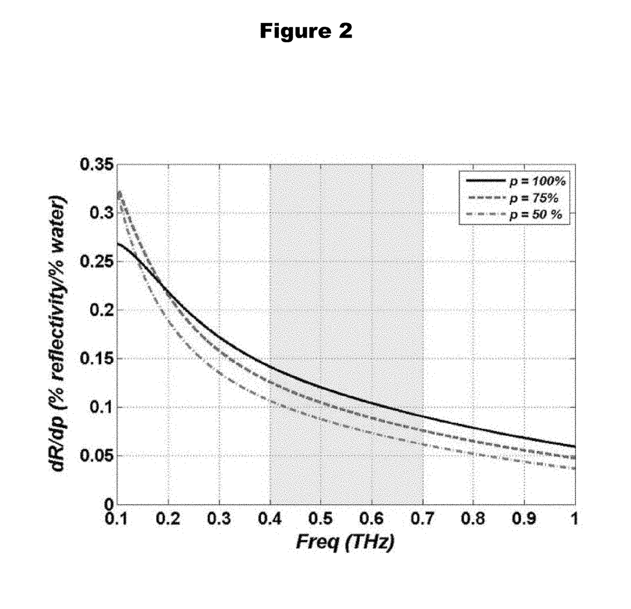
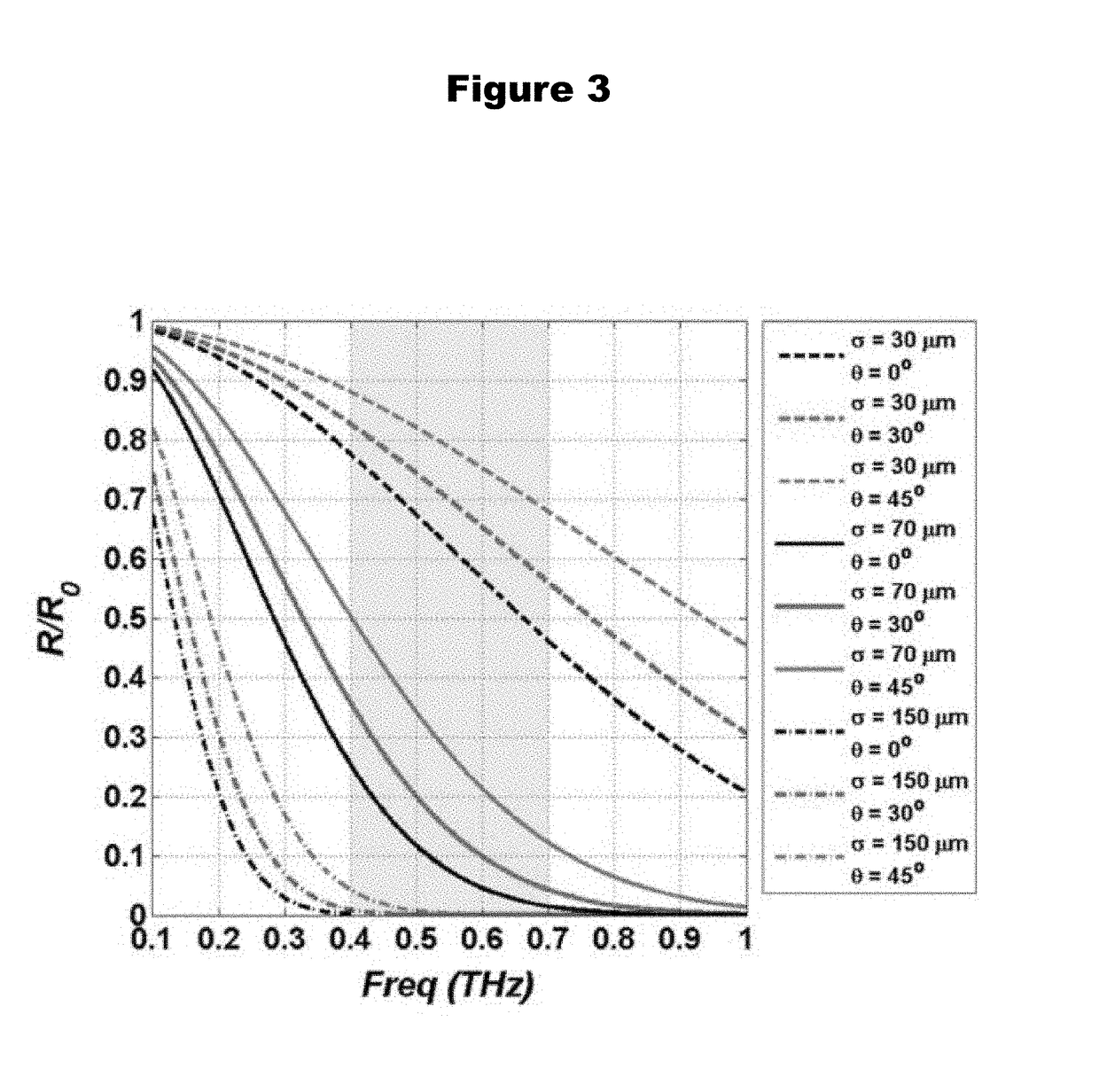
[0129]Various prior art has commented on the accuracy of using the double Debye model as a baseline and perturbing the relaxation time until the fit converges with the observed spectra (D. B. Bennett, et al., IEEE Sens. J., 11(5):1253-62, 2011; H. J. Liebe, G. A. Hufford, and T. Manabe, “Int. J. Infrared Millim. Waves, 12(7):659-75, 1991; E. Pickwell, et al., Appl. Phys. Lett., 84(12):2190-92, 2004; Z. D. Taylor, et al., IEEE Trans. Terahertz Sci. Technol., 5(2):170-83, 2015; A. Maccabi, et al., 8585:85850X-85850X-, 2013; the disclosures of which are incorporated herein by reference). Here, in accordance with various embodiments, it is proposed to employ effective media theory to compute tissue dielectric properties through the use of the estimated fill factor of water to tissue. When the tissue water content is changed by thermal insult and the subsequent physiologic response, the fill factor can be modified to compute the effective ...

example 3

vo Imaging in Pre-Clinical Rat Model

[0139]To test various embodiments of the invention, rats were used as an pre-clinical model for in vivo THz burn wound imaging (W. A. Dorsett-Martin, Wound Repair Regen., 12(6):591-99, 2004, the disclosure of which is incorporated herein by reference). Among the available burn wound parameters, skin thickness is most pertinent for understanding the wound depth as an aspect of wound healing. The thicknesses of rat and human skin layers are most similar compared to those of other animal skin (Table 3), and therefore rats are frequently used as cutaneous injury models (T. N. Meyer and A. L. da Silva, “Acta Cirúrgica Bras., 14(4):0-0, 1999; R. K. Cribbs, M. H. Luquette, and G. E. Besner, J. Surg. Res., 80(1):69-74, 1998; T. Kaufman, et al., Burns, 16(1):13-16, 1990; J. S. Knabl, et al., Burns, 25(3):229-35, 1999; the disclosures of which are incorporated herein by reference). In addition to the availability of a broad knowledge base on rat wound heali...


PUM


Abstract

Systems, methods and apparatuses for performing wound analysis using THz imaging are provided. Due to the large complex component of water's dielectric constant in the THz regime, and the relative frequency invariance of non-aqueous tissue constituents, this modality is highly sensitive to the water content of tissue. It has been found that using THz imaging turns the presence of edema into a contrast mechanism, and allows for the use of the spatial distributions of edema to assess wound status immediately. Apparatus and methods enable earlier diagnosis of wound status which could result in accelerated treatment and shorter overall hospital stays.

Description

STATEMENT OF FEDERAL FUNDING[0001]This invention was made with Government support under Grant No. 1 R21 EB016896-01A1 and 1 R21 EB015084, awarded by the National Institutes of Health. The Government has certain rights in the invention.FIELD OF THE INVENTION[0002]The present invention relates to spatially resolved hydration mapping enabled by THz imaging capable of forming highly sensitive contrast maps for wound analysis, which may include of assessment of severity or viability.BACKGROUND OF THE INVENTION[0003]Wounds are a serious public health issue. The worldwide burden of surgical wounds and burn injuries is estimated to be ˜40-50 million and ˜7-10 million people, respectively (K. F. Cutting, R. J. White, and P. Mahoney, “Int. Wound J., 10(1):79-86, 2013, the disclosure of which is incorporated herein by reference). Early and accurate assessment of a wound and / or its healing potential are the most important determinants of the therapeutic management of patients sustaining a cutan...

Claims


Application Information

Patent Timeline
Patent Type & Authority Applications(United States)
IPC IPC(8): A61B5/05A61B5/00
CPCA61B5/0507A61B5/445A61B5/0035A61B5/0077A61B5/4878A61B5/0075A61B5/0066A61B5/0002A61B5/055A61B5/00A61B5/05G01B11/24A61B3/101
Inventor NOWROOZI, BRYANGRUNDFEST, WARREN S.TAYLOR, ZACHARYGARRITANO, JAMESTEWARI, PRIYAMVADASUNG, SHIJUNBAJWA, NEHA
Owner RGT UNIV OF CALIFORNIA
Learn More