Grinding apparatus

a technology of grinding apparatus and grinding wheel, which is applied in the direction of grinding machine components, manufacturing tools, lapping machines, etc., can solve the problems of large wear amount difficult grinding, and increased production costs, so as to reduce wear of grinding wheel grindstone, reduce production costs, and enhance the cooling effect of grinding water

Active Publication Date: 2019-02-28
DISCO CORP
View PDF0 Cites 0 Cited by
  • Summary
  • Abstract
  • Description
  • Claims
  • Application Information

AI Technical Summary

Benefits of technology

[0004]It is therefore an object of the present invention to restrain excessive wear of a grindstone and to enable smooth grinding, in the case of grinding a wafer formed of a difficultly grindable material or a wafer including a metal.
[0008]In the grinding apparatus according to the present invention, the grinding wheel has the grindstone formed by binding abrasive grains with the bonding agent, and the grinding apparatus includes: the grinding water supply unit that supplies grinding water to at least the grindstone when the workpiece held by the holding table is ground by the grinding unit; the light applying unit that is disposed adjacent to the holding table and that applies light to the grinding surface of the grindstone grinding the workpiece held by the holding table; and the light applying unit moving section by which the light applying unit can be positioned at the first position on the rotational trajectory of the grinding wheel mounted to the spindle in the case where the grinding wheel has the first diameter and the second position on the rotational trajectory of the grinding wheel in the case where the grinding wheel has the second diameter. Therefore, it is possible to position the light applying unit at an appropriate position according to the diameter of the grinding wheel possessed by the grinding unit, to efficiently make hydrophilic or the like the grindstone cutting into the workpiece, thereby to enhance a cooling effect of grinding water, to restrain wearing of the grindstone, and to enhance a swarf discharging property. Further, with the grindstone made hydrophilic or the like, grinding water is effectively supplied into the processing region where the grindstone grinds the workpiece, and, therefore, processing quality can be prevented from being lowered due to processing heat, and smooth grinding can be achieved even in the case where the workpiece is a wafer formed of a difficultly grindable material.
[0009]In addition, where the grindstone is formed by binding the abrasive grains and the photocatalyst grains with the bonding agent and the light applying unit applies light that excites the photocatalyst grains, it is ensured that the grinding water supplied exhibits an oxidizing power due to hydroxyl radicals. Therefore, even if the workpiece is a wafer formed, for example, of a difficultly grindable material, it is possible to oxidize the surface to be ground of the workpiece by the strong oxidizing power of the thus produced hydroxyl radicals, to perform grinding while embrittling the surface through the oxidation, and to smoothly grind the workpiece. Similarly, even when the workpiece is a wafer formed of a metal or a wafer in which metallic electrodes are partly exposed at the surface to be ground of the wafer, grinding can be performed while embrittling the metal through oxidation by the strong oxidizing power of hydroxyl radicals, and, therefore, the workpiece can be ground smoothly.
[0010]With the vitrified bond used as the bonding agent in the grindstone, the property of making hydrophilic or the like the grinding surface of the grindstone by application of light thereto can be enhanced more.

Problems solved by technology

In the case where the wafer is formed of a difficultly grindable material such as gallium nitride (GaN), silicon carbide (SiC) or gallium arsenide (GaAs), there is a problem that the wearing amount of a grindstone of a grinding wheel is large and production cost is raised thereby.
In addition, in the case of grinding a wafer formed of a metal or a wafer in which metallic electrodes are partly exposed at a surface to be ground of the wafer, there is a problem that ductility of the metal makes it difficult to perform grinding.

Method used


Image

  • Grinding apparatus
  • Grinding apparatus
  • Grinding apparatus

Examples


Embodiment Construction

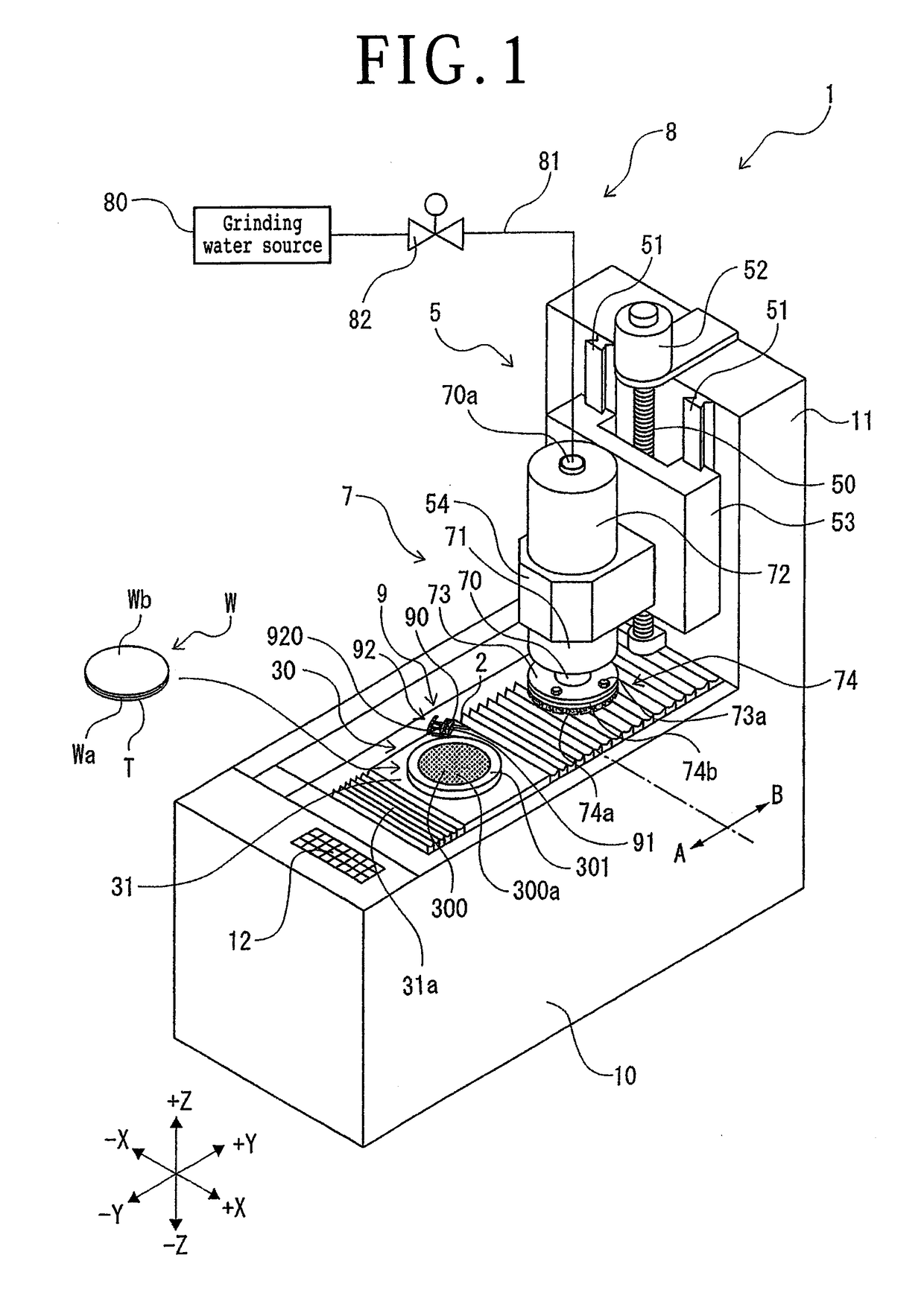
[0021]A grinding apparatus 1 depicted in FIG. 1 is an apparatus that grinds a workpiece W held on a holding table 30 by a grinding unit (grinding means) 7 provided with a grinding wheel 74. A front side (−Y direction side) on a base 10 of the grinding apparatus 1 is a mounting / detaching region A in which the workpiece W is mounted onto and detached from the holding table 30, and a rear side on the base 10 is a grinding region B in which grinding of the workpiece W is conducted by the grinding unit 7. Input means 12 through which an operator inputs processing conditions and the like to the grinding apparatus 1 is disposed on the front side on the base 10.

[0022]The holding table 30 is, for example, circular in outer shape, and includes a suction holding section 300 that holds the workpiece W by suction, and a frame body 301 that supports the suction holding section 300. The suction holding section 300 communicates with a suction source (not depicted), and the workpiece W is suction he...


PUM


Abstract

A grinding apparatus includes a table that holds a workpiece, and a grinding unit including a grinding wheel mounted to a spindle. The grinding wheel has a grindstone formed by binding abrasive grains with a bonding agent. In addition, the grinding apparatus further includes: a grinding water supply unit that supplies grinding water to at least the grindstone; a light applying unit that is disposed adjacent to the table and that applies light to a grinding surface of the grindstone grinding the workpiece held by the table; and a light applying unit moving section by which the light applying unit can be positioned at a first position on a rotational trajectory of the grinding wheel in the case where the grinding wheel has a first diameter and a second position on a rotational trajectory of the grinding wheel in the case where the grinding wheel has a second diameter.

Description

BACKGROUND OF THE INVENTIONField of the Invention[0001]The present invention relates to a grinding apparatus including a holding table that holds a workpiece, and a grinding unit (grinding means) having a grinding wheel for grinding the workpiece held by the holding table.Description of the Related Art[0002]A plate-shaped workpiece such as a semiconductor wafer is ground by a grinding apparatus (see, for example, Japanese Patent Laid-open No. 2001-284303) to be thinned to a predetermined thickness, and is thereafter divided by a cutting apparatus or the like into individual device chips, which are utilized for various electronic apparatuses and the like.SUMMARY OF THE INVENTION[0003]In the case where the wafer is formed of a difficultly grindable material such as gallium nitride (GaN), silicon carbide (SiC) or gallium arsenide (GaAs), there is a problem that the wearing amount of a grindstone of a grinding wheel is large and production cost is raised thereby. In addition, in the cas...

Claims


Application Information

Patent Timeline
Patent Type & Authority Applications(United States)
IPC IPC(8): H01L21/304B24B5/04B24B55/02B24B5/307B24B7/22
CPCH01L21/304B24B5/045B24B55/02B24B5/307B24B7/228B24B37/10B24B37/34H01L21/02013B24B37/04B24B37/24B24B49/12B24B55/03B24D3/14
Inventor TAKENOUCHI, KENJIGAWAZAWA, TAKAYUKI
Owner DISCO CORP
Why Eureka
Try Eureka