
Method of estimating deteriorated state of secondary battery and secondary battery system

a secondary battery and deteriorated state technology, applied in secondary cells, battery servicing/maintenance, instruments, etc., can solve the problems of high probability of deterioration, inability to accurately estimate the impedance, and uneven concentration distribution of salt concentration in the electrolyte, so as to improve the estimation accuracy and improve the estimation accuracy

Active Publication Date: 2019-02-28
TOYOTA JIDOSHA KK
View PDF0 Cites 14 Cited by
  • Summary
  • Abstract
  • Description
  • Claims
  • Application Information

AI Technical Summary

Benefits of technology

The patent aims to improve the accuracy of estimating the deteriorated state of a secondary battery used in vehicles. The method takes into account the current, temperature, and state of charge (SOC) of the battery during the measurement period to accurately calculate the impedance of the battery. This helps to reflect the impact of these factors on the battery's performance and increase the accuracy of estimating the battery's condition. The method also proposes a criterion for when to stop or resume calculating the impedance component for each frequency bandwidth, ensuring optimal accuracy and opportunities for calculation. In summary, this patent provides a method to more accurately estimate the state of a vehicle's secondary battery.

Problems solved by technology

In such a case, influence by dependency on a current, a temperature, or an SOC may not accurately be reflected on an impedance and the impedance may not highly accurately be calculated.
According to the method, when the parameter is higher than the reference value, calculation of an impedance component for each frequency bandwidth is prohibited, with such determination being made that unevenness of the temperature distribution in the secondary battery, unevenness of the salt concentration distribution in the electrolyte, or unevenness of the concentration distribution of the charge transport material in the active material has highly likely occurred.

Method used


Image

  • Method of estimating deteriorated state of secondary battery and secondary battery system
  • Method of estimating deteriorated state of secondary battery and secondary battery system
  • Method of estimating deteriorated state of secondary battery and secondary battery system

Examples


first embodiment

[0044]

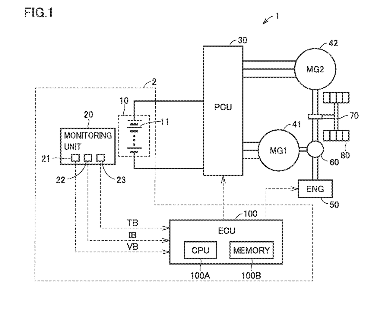
[0045]FIG. 1 is a diagram schematically showing an overall configuration of a vehicle on which a secondary battery system according to a first embodiment is mounted. Referring to FIG. 1, a vehicle 1 is representatively a hybrid vehicle. A battery system according to the present disclosure, however, is applicable to general vehicles which generate motive power with electric power supplied from a secondary battery system, without being limited to the hybrid vehicle (including a plug-in hybrid vehicle). Therefore, vehicle 1 may be an electric vehicle or a fuel cell vehicle.

[0046]Vehicle 1 includes a secondary battery system 2, a power control unit (PCU) 30, motor generators 41 and 42, an engine 50, a power split device 60, a driveshaft 70, and a drive wheel 80. Secondary battery system 2 includes a battery 10, a monitoring unit 20, and an electronic control unit (ECU) 100.

[0047]Engine 50 is an internal combustion engine which outputs motive power by converting combustion energy g...

first modification

of First Embodiment

[0105]In order to calculate an impedance component in the high-frequency bandwidth, a period for sampling of data should be short. For example, in calculating an impedance component at a frequency of 1 kHz, the sampling period is set to 1 ms or shorter (preferably 0.5 ms or shorter). For calculation of an impedance component in the low-frequency bandwidth, data should be obtained (sampled) for a long period and stored in memory 100B. For example, in order to calculate an impedance component at a frequency of 10 mHz, data for at least one hundred seconds should be stored in memory 100B.

[0106]When calculation of both of an impedance component in the high-frequency bandwidth and an impedance component in the low-frequency bandwidth is required, for example, data for one hundred seconds or longer obtained with a sampling period not longer than 1 ms may be stored in memory 100B. In that case, however, memory 100B of a large capacity is required and cost for members may...

second modification

of First Embodiment

[0122]It is not essential to always calculate impedance components in all frequency bandwidths of the low-frequency bandwidth, the medium-frequency bandwidth, and the high-frequency bandwidth. A configuration in which a period during which an impedance component in some frequency bandwidth is not calculated is provided will be described in a second modification of the first embodiment.

[0123]FIGS. 13A to 13C are conceptual diagrams for illustrating a technique of obtaining data in the second modification of the first embodiment. Referring to FIG. 13A, in the second modification, low-frequency impedance component ZL is steadily calculated. During a data acquisition period in which only low-frequency impedance component ZL is calculated, a relatively long (sparse) sampling period is set.

[0124]High-frequency impedance component ZH is calculated, for example, only once each time m (m being a natural number not smaller than two) data acquisition periods elapse. As a tim...


PUM


Abstract

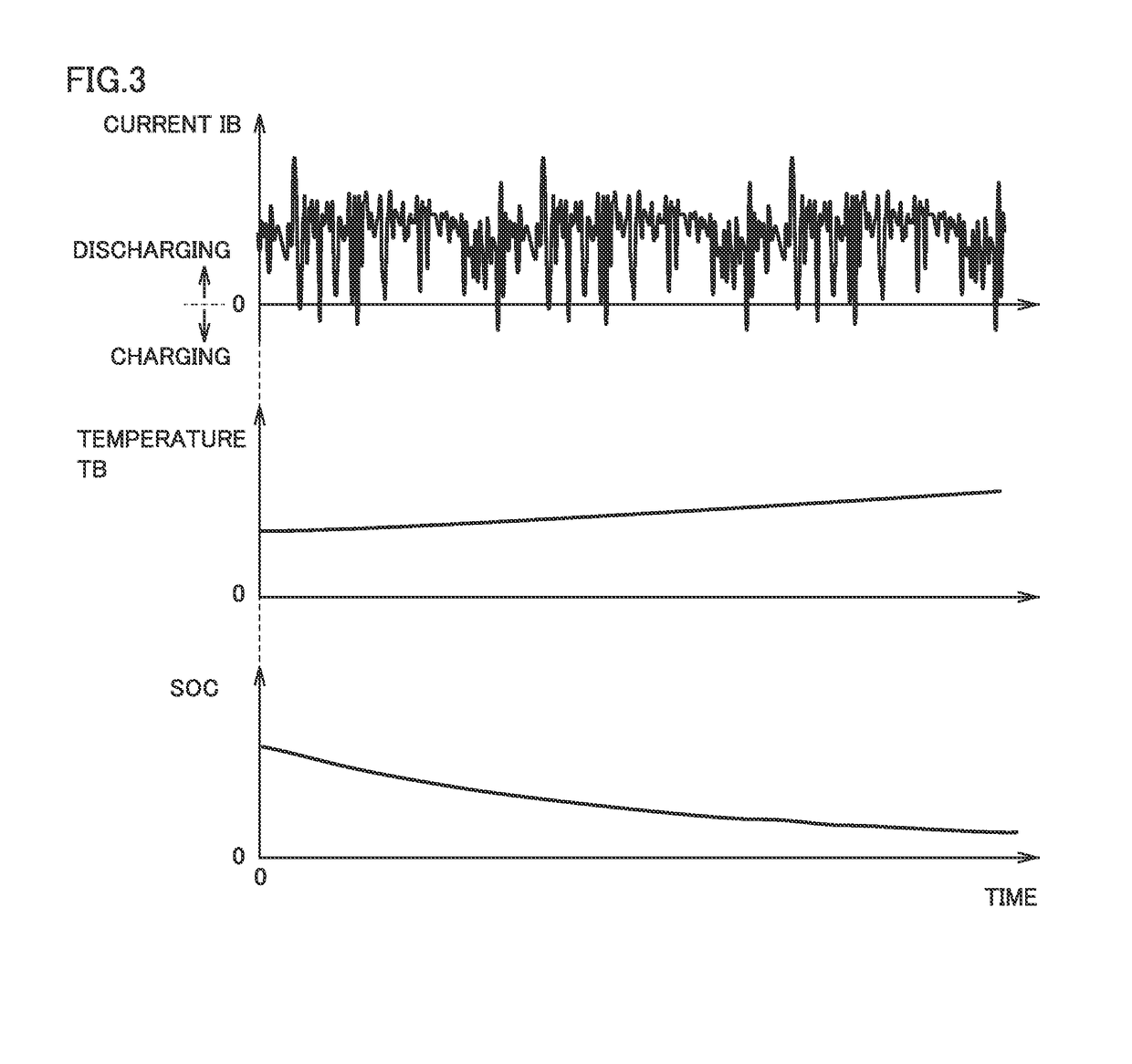
A method of estimating a deteriorated state of a battery includes steps S102 to S110. S102 is a step of obtaining a voltage and a current of the battery a plurality of times for a data acquisition period. S104 is a step of calculating an amount of change in current, an amount of change in temperature, and an amount of change in SOC during the data acquisition period. S106 is a step of obtaining an allowable amount of change in current, an allowable amount of change in temperature, and an allowable amount of change in SOC based on an average temperature. S110 is a step of calculating an impedance component for each frequency bandwidth based on the voltage and the current by subjecting the voltage and the current to Fourier transform when all amounts of change are smaller than the allowable amounts of change.

Description

[0001]This nonprovisional application is based on Japanese Patent Application No. 2017-159955 filed with the Japan Patent Office on Aug. 23, 2017, the entire contents of which are hereby incorporated by reference.BACKGROUNDField[0002]The present disclosure relates to a method of estimating a deteriorated state of a secondary battery and a secondary battery system and more particularly to a secondary battery deteriorated state estimation method of estimating a deteriorated state of a secondary battery mounted on a vehicle and a secondary battery system used as being mounted on a vehicle.Description of the Background Art[0003]Vehicles incorporating secondary batteries for running have increasingly been used in recent years. Since the secondary batteries mounted on such vehicles may deteriorate in accordance with how they are used or an environment where they are used or with lapse of time, highly accurate estimation of a deteriorated state (state of health (SOH)) of the secondary batt...

Claims


Application Information

Patent Timeline
IPC IPC(8): G01R31/36B60L11/18H01M10/42H01M10/617
CPCB60L11/1861H01M10/617G01R31/3842G01R31/392H01M10/425H01M10/48H01M10/42H01M2220/20H01M10/625H01M10/633G01R31/367G01R31/374G01R31/007B60L3/12B60L2240/545B60L2240/549B60L2240/547B60L58/13B60L58/14B60L58/21H02J7/0013H02J7/005B60L58/12H02J7/0024
Inventor HAGA, NOBUYASUHAMAGUCHI, HIROSHIKANADA, RYOSOEJIMA, TAKANORI
Owner TOYOTA JIDOSHA KK
Learn More