
Actuator driver

a technology of image capture apparatus and actuator, which is applied in the direction of color television details, television systems, instruments, etc., can solve the problem that the arrangement is not capable of correcting the lens position with high precision, and achieve the effect of high precision

Active Publication Date: 2019-02-07
ROHM CO LTD
View PDF2 Cites 4 Cited by
  • Summary
  • Abstract
  • Description
  • Claims
  • Application Information

AI Technical Summary

Benefits of technology

The present invention seeks to provide an image capture apparatus that can position the lens with high precision, even during acceleration. The corrective arrangement reduces the effects of gravity and inertia, and combines the correction based on the first acceleration information with open-loop control operation, improving stability with respect to external force. The correction based on the first acceleration information may be used for autofocus lens position control, while the correction based on the first and second acceleration information may be used for image stabilization correction. These improvements lead to improved performance and stability of the image capture apparatus.

Problems solved by technology

When the image capture apparatus is subjected to acceleration, this arrangement is not capable of correcting the lens position with high precision.

Method used


Image

  • Actuator driver
  • Actuator driver
  • Actuator driver

Examples


first embodiment

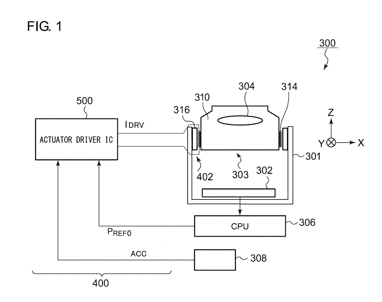
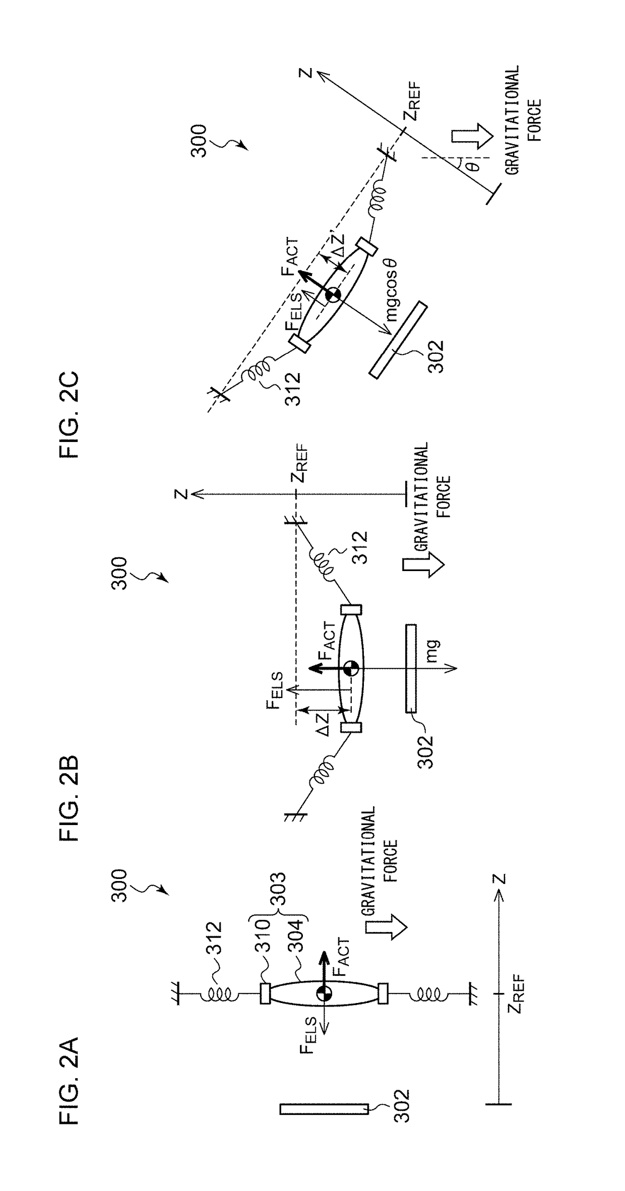
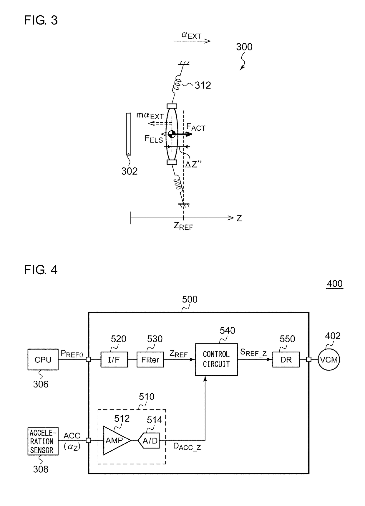
[0035]Description will be made in the present embodiment regarding an image capture apparatus. FIG. 1 is an image capture apparatus 300 according to a first embodiment. The image capture apparatus 300 is configured as a digital still camera, a digital video camera, or a camera module built into a smartphone or a tablet terminal. The image capture apparatus 300 includes an image sensor 302, a lens 304, a processor 306, an acceleration sensor 308, and a lens control apparatus 400. The lens 304 is arranged on an optical axis of light to be input to the image sensor 302. The lens 304 is configured as an autofocus (AF) lens. The lens control apparatus 400 sets the position of the lens 304 in the optical axis direction (Z-axis direction) thereof according to a position instruction value (which will also be referred to as a “target code”) PREF0 received from the processor 306.

[0036]The processor 306 generates the position instruction value PREF0 such that an image captured by the image sen...

second embodiment

[0085]Description has been made in the first embodiment regarding the correction of an external force in an autofocus control operation. Also, the present invention may be applied to an image stabilization system.

[0086]FIG. 8 is a diagram showing an image capture apparatus 300A according to a second embodiment. Description will be made regarding the configuration of the image capture apparatus 300A directing attention to the points of difference from the image capture apparatus 300 shown in FIG. 1. The image capture apparatus 300A includes an image stabilization function in addition to an autofocus function. An actuator 402A is configured to support positioning of the movable portion 303 in two directions (X-axis direction and Y-axis direction) that are each orthogonal to the optical-axis direction (Z-axis direction) independently of and in addition to the optical-axis direction. Specifically, the actuator 402A includes an X-direction coil and a Y-direction coil (not shown) for an O...


PUM


Abstract

An actuator positions a movable portion including a lens in a first direction (Z-axis direction). An acceleration sensor generates first acceleration information ACC that indicates the acceleration applied to the image capture apparatus in the first direction. An actuator driver IC superimposes a correction value that corresponds to the first acceleration information on a base instruction value that corresponds to the target position to be set for the lens in the first direction. The actuator driver IC controls the actuator according to a corrected instruction value thus obtained.

Description

CROSS-REFERENCE TO RELATED APPLICATION[0001]The present application claims priority under 35 U.S.C. § 119 to Japanese Patent Application No. 2017-149229, filed on Aug. 1, 2017, the entire contents of which are incorporated herein by reference.BACKGROUND OF THE INVENTION1. Field of the Invention[0002]The present invention relates to an actuator driver and an image capture apparatus employing the actuator driver.2. Description of the Related Art[0003]In recent years, in almost all cases, a mobile device such as a cellular phone terminal, tablet terminal, or the like, mounts a camera. In particular, in the great majority of cases, such a camera has an autofocus (AF) function. Typically, such a camera having an AF function includes an actuator for adjusting the extension position of a lens according to the position of the subject. As such an actuator, actuators employing a voice coil motor (VCM) method have become mainstream. Also, various kinds of methods have been proposed and develop...

Claims


Application Information

Patent Timeline
Patent Type & Authority Applications(United States)
IPC IPC(8): H04N5/225H04N5/232G02B7/04
CPCH04N5/2254H04N5/23212G02B7/04H04N5/2252G02B7/08G02B27/646H04N23/51H04N23/55H04N23/67H04N23/6812H04N23/687
Inventor TANIMUKAI, HIROMICHISAITO, AKIHITOMAEDE, JUNSEKIMOTO, YOSHIHIRO
Owner ROHM CO LTD
Learn More