
Machining system, apparatus and method

a technology of machining system and gear, applied in the direction of heat treatment apparatus, gear teeth, furnaces, etc., can solve the problems of unintentional radiusing of edges or tips, affecting the operation or functionality of workpieces, and creating unwanted noise, so as to reduce the effect of radiused tips, and provide rough gear surfaces

Active Publication Date: 2019-01-31
ENGINEERED ABRASIVES
View PDF1 Cites 0 Cited by
  • Summary
  • Abstract
  • Description
  • Claims
  • Application Information

AI Technical Summary

Benefits of technology

The present invention relates to a method and apparatus for processing metallic workpieces with defined edges, such as gears, to increase root strength and reduce radiused tips on the workpiece. The method involves media blasting the workpiece with a first media to increase root strength, and then subjecting the workpiece to a finishing process with a second media to reduce or eliminate radiused tips. The finishing process may be performed using a spindle-finishing apparatus or a vibration finishing process. The invention provides higher strength gears with reduced radiused tips on their tips or edges.

Problems solved by technology

When a workpiece includes sharp or distinct edges, such as the tip of a gear tooth, those edges or tips may be unintentionally radiused from the blasting of the peening material, such that a mushroom effect occurs on the edge or tip of the gear tooth.
This mushroom effect may alter the operation or functionality of the workpiece.
Even if the mushroom effect does not alter the operation or functionality of the workpiece, it may create unwanted noise when the workpiece engages with other components during operation.

Method used


Image

  • Machining system, apparatus and method
  • Machining system, apparatus and method
  • Machining system, apparatus and method

Examples


Embodiment Construction

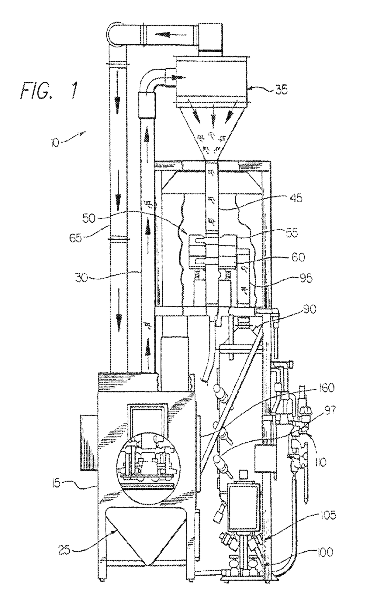
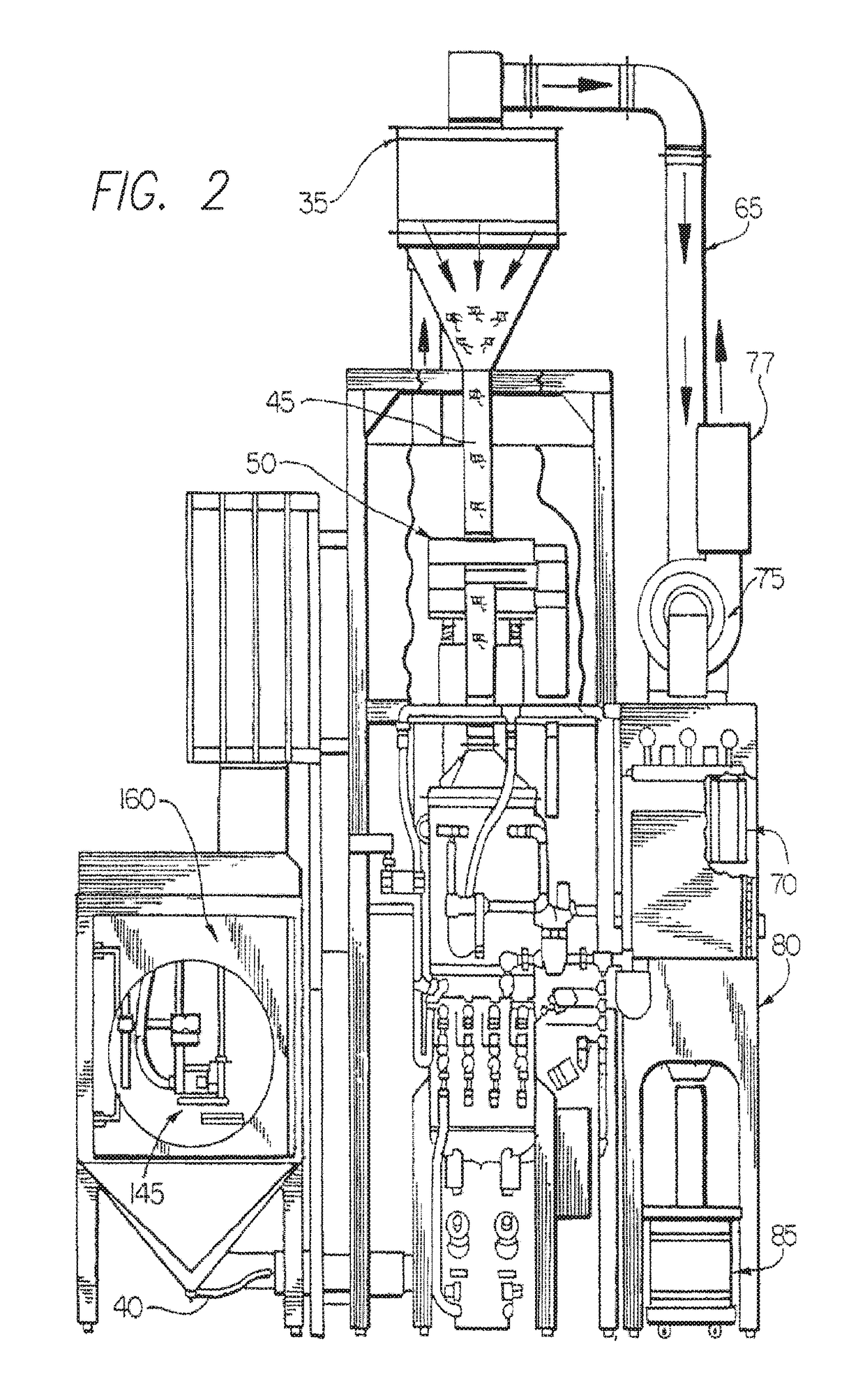
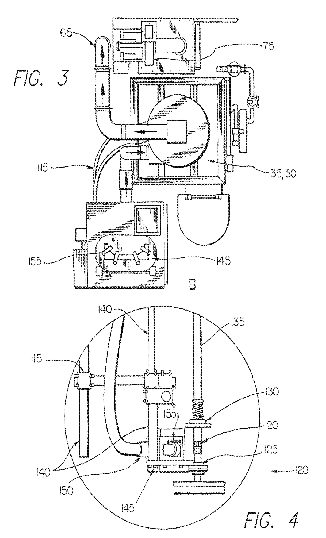
[0021]Referring now to the drawings, FIGS. 1-4 illustrate a first media blasting apparatus according to the invention, generally indicated by the number 10. FIGS. 5-6 illustrated a second finishing apparatus according to the invention, generally indicated by the number 200. FIGS. 8A, 9A and 10A illustrate a teeth-portion of a workpiece prior to the workpiece being subjected to processing in the first media blasting apparatus 10. FIGS. 8B, 9B and 10B illustrate the teeth-portion of the workpiece after processing in the first media blasting apparatus 10 but before it is subjected to processing in the second finishing apparatus 200.

[0022]The first media blasting apparatus 10 will now be described. As illustrated, the first media blasting apparatus 10 includes a blasting cabinet or chamber 15, in which a stream of media is directed against a workpiece 20. Such media may comprise, for example, cut wire, glass beads, ceramic beads or fine steel beads. The cabinet 15 is connected to a cabi...


PUM

PropertyMeasurementUnit
separationaaaaaaaaaa
efficiency of separationaaaaaaaaaa

Abstract

A method and apparatus for processing a metallic workpiece with defined edges (e.g., a gear) comprises media blasting of the workpiece by directing a first media against exposed surfaces on the workpiece to increase the root strength of the gear, the blasting causing the defined edges to be radiused or mushroomed, ceasing the media blasting, loading the workpiece into a finishing apparatus, and subjecting the workpiece to a finishing process with a second media, the exposed surfaces on the workpiece being subjected to the finishing process to reduce the radiused edges on the workpiece created from the media blasting. The process of moving the workpiece to the spindle-finishing apparatus from the media blasting may be performed automatically by a machine. Once the workpiece has been subjected to the finishing process with the second media, it may be removed from the spindle-finishing machine, washed, and rinsed with rust inhibitor whereby wear properties of the workpiece are enhanced.

Description

CROSS REFERENCE TO RELATED APPLICATIONS[0001]This application is a Divisional of co-pending U.S. patent application Ser. No. 15 / 157,816, filed May 18, 2016, which claims the benefit of priority under 35 U.S.C. § 119(e) to U.S. Provisional Patent Application No. 62 / 186,042, filed Jun. 29, 2015. The disclosures set forth in the referenced applications are incorporated herein by reference in their entirety.BACKGROUND OF THE INVENTION[0002]This invention relates generally to a method for media blasting and finishing a gear or other workpiece or part. The powered part hold-down apparatus of U.S. Pat. No. 5,272,897 may be used for the peening step(s) of the present disclosure, and the disclosure of the U.S. Pat. No. 5,272,897 patent is hereby incorporated in its entirety by this reference. Elements of other known methods of media blasting and finishing, such as the peen finishing method and apparatus of U.S. Pat. No. 8,453,305, may be used for the present disclosure, and the disclosure of...

Claims


Application Information

Patent Timeline
Patent Type & Authority Applications(United States)
IPC IPC(8): B23P15/14B23F19/00C21D9/32C21D7/06C22F1/00B24B39/00B24C1/08B24C1/10B24C11/00B23F19/10B24B31/02
CPCB23F19/00C21D9/32C21D7/06B23P15/14C22F1/00B24B39/006B24C1/083B24C1/10B24C11/00B23F19/10B24B31/02
Inventor WERN, MICHAEL J.
Owner ENGINEERED ABRASIVES
Learn More