A method of forming dust-removal holes for a turbine blade, and an associated ceramic core

Active Publication Date: 2019-01-24
SAFRAN
View PDF0 Cites 6 Cited by
  • Summary
  • Abstract
  • Description
  • Claims
  • Application Information

AI Technical Summary

Benefits of technology

The present invention proposes a new geometrical arrangement of the core that makes it easier to create dust-removing holes, while maintaining the mechanical strength of the core. This arrangement also eliminates the need for drilling the bathtub to obtain such holes, which has previously been a final operation in the prior art. The core serves to improve the mechanical properties of the blade and eliminates uncertainties during casting. Additionally, the invention provides a setback zone for centering the through orifice in the connection zone and adding lateral stiffeners to improve the strength of the core during casting.

Problems solved by technology

The air needed for operation of the engine generally contains various kinds of dust (in particular fine sand) that can accumulate in the cooling circuits of turbine blades thereby leading to the discharge orifices at the outlets from the cavities becoming closed, and thus threatening the integrity of the blades.
Nevertheless, using such connection rods raises certain problems.
Firstly, alumina rods are very difficult to eliminate with basic solutions (or under standard knock-out conditions for ceramic cores), requiring longer reaction times, very high concentrations of sodium hydroxide or of potassium hydroxide, and very high temperatures and pressures that can be aggressive for the alloy (corrosion under stress).
Likewise, quartz rods present low mechanical strength, which penalizes their use in a lost wax casting method in which the core is subjected to various mechanical stresses since it possesses a different coefficient of thermal expansion (CTE) and is also often of different composition.
Furthermore, the use of rods is not applicable in all methods of fabricating cores.
For example, with cores prepared by additive manufacturing or cores obtained by machining a ceramic block, the rods cannot be embedded in the core during fabrication (unlike fabrication by the injection molding method).
Finally, the use of rods is not applicable to all geometrical shapes of core, in particular those involving thin plates of shape to which the rods must fit closely.
Unfortunately, such brazed plates are not robust (they can become detached and it may thus be necessary to thicken them locally) and surfacing is often not accurate (plugging depth uncertain).
Under such circumstances, it is found to be particularly difficult to drill connection rods forming the dust-removal holes since such calibrated drilling takes place in a location that has previously been plugged, and that therefore has a smaller diameter while nevertheless complying with the specified minimum diameter for discharging debris.

Method used


Image

  • A method of forming dust-removal holes for a turbine blade, and an associated ceramic core
  • A method of forming dust-removal holes for a turbine blade, and an associated ceramic core
  • A method of forming dust-removal holes for a turbine blade, and an associated ceramic core

Examples


Embodiment Construction

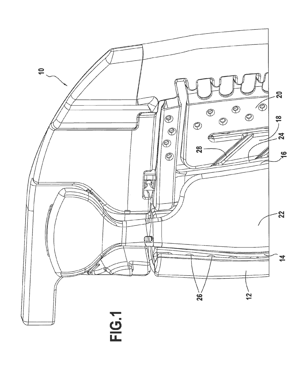
[0019]FIG. 1 shows, the tip assembly of a ceramic core for use in making a hollow turbine blade of a turbine engine. In the example shown, the ceramic core 10 comprises seven portions or columns. The first column 12, which is to be located on the side where the combustion gas arrives, corresponds to a leading edge cavity that is to be created after casting, whereas the second column 14 corresponds to a central cavity that is adjacent thereto. This cavity receives a stream of cooling air via a channel that results, after casting, from the presence of a first column root of the core. Three other columns 16, 18, and 20 correspond to adjacent cavities that receive a second stream of cooling air via another channel coming from the presence of a second column root of the core. Finally, the core also has sixth and seventh columns 22 and 24 constituting side columns and corresponding to side cavities created after casting, being respectively spaced apart from the second and third columns 14...


PUM


Abstract

A ceramic core used for fabricating a hollow turbine blade for a turbine engine using the lost wax casting technique, the blade including calibrated dust-removal holes emanating from a top of at least one cavity and opening out into a bathtub of the blade, wherein each of the calibrated dust-removal holes is formed in a core portion of height that is determined to be sufficient to guarantee mechanical strength, the core portion including a through orifice of axis perpendicular to a longitudinal axis of the calibrated dust-removal hole and defining on either side of the through orifice firstly a core cylinder having a determined diameter corresponding to the dust-removal hole that is to be formed, and secondly a remaining core volume that is to be plugged after casting, such that the calibrated dust-removal hole is obtained without drilling and without using connection rods.

Description

FIELD OF THE INVENTION[0001]The present invention relates to the general field of sets of blades for a turbine engine turbine, and more particularly to turbine blades having cooling circuits incorporated therein made by the lost-wax casting technique.PRIOR ART[0002]In known manner, a turbine engine includes a combustion chamber in which air and fuel are mixed together prior to being burnt therein. The gas resulting from such combustion flows downstream from the combustion chamber and then feeds a high-pressure turbine and a low-pressure turbine. Each turbine comprises one or more rows of stationary vanes (referred to as nozzles) alternating with one or more rows of moving blades (referred to as rotor wheels), that are spaced apart circumferentially all around the rotor of the turbine. Such turbine blades and vanes are subjected to the very high temperatures of the combustion gas, which reach values well above those that can be withstood without damage by such blades or vanes that ar...

Claims


Application Information

Patent Timeline
IPC IPC(8): B22C9/10F01D5/18
CPCB22C9/10F01D5/187F05D2230/211F05D2260/607
Inventor ROLLINGER, ADRIEN BERNARD VINCENTBECHELANY, MIRNA
Owner SAFRAN
Why Eureka
Try Eureka