Priming pump for a circuit subjecting said pump to an outlet pressure greater than an inlet pressure

Inactive Publication Date: 2006-03-02
PROUST NATHALIE
View PDF10 Cites 1 Cited by
  • Summary
  • Abstract
  • Description
  • Claims
  • Application Information

AI Technical Summary

Benefits of technology

[0010] Thus, the greater leakage rate on the outlet side enables the pressure that exists at the outlet of the pump to become dominant in the priming pump. Since the outlet pressure is greater than atmospheric pressure, the priming pump is maintained under pressure, thus keeping its envelope in its inflated position and preventing it from collapsing under the effect of the suction that exists in the feed line to the injector pump.
[0014] This disposition makes it simple to obtain asymmetry in the residual leakage rates between the endpieces.

Problems solved by technology

Unfortunately, the valve members in the endpieces are never perfectly seated against their seats, and each of them therefore presents a residual leakage rate.
Depending on which one of the valve members presents the greater leakage rate during operation of the engine, the priming pump can be subjected either to excess pressure, in which case it will become slightly inflated, or else to suction, in which case it runs the risk of collapsing.
This can be particularly troublesome.
Since the pump is located in an environment that is very hot, it runs the risk of becoming progressively thermoformed in the position that it occupies while the engine is running.
However, being thermoformed in the collapsed position makes the pump unusable.

Method used


Image

  • Priming pump for a circuit subjecting said pump to an outlet pressure greater than an inlet pressure
  • Priming pump for a circuit subjecting said pump to an outlet pressure greater than an inlet pressure

Examples


Embodiment Construction

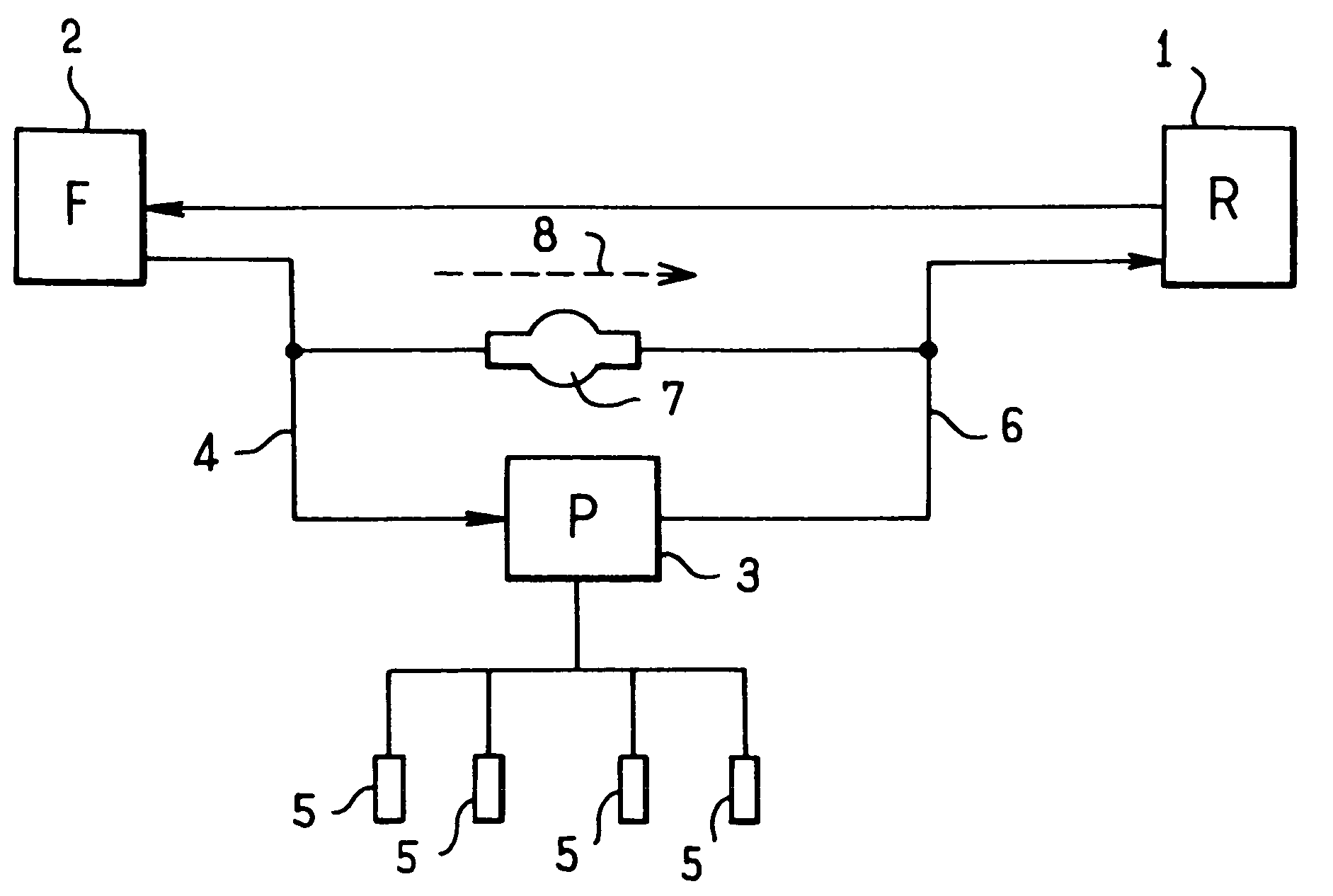
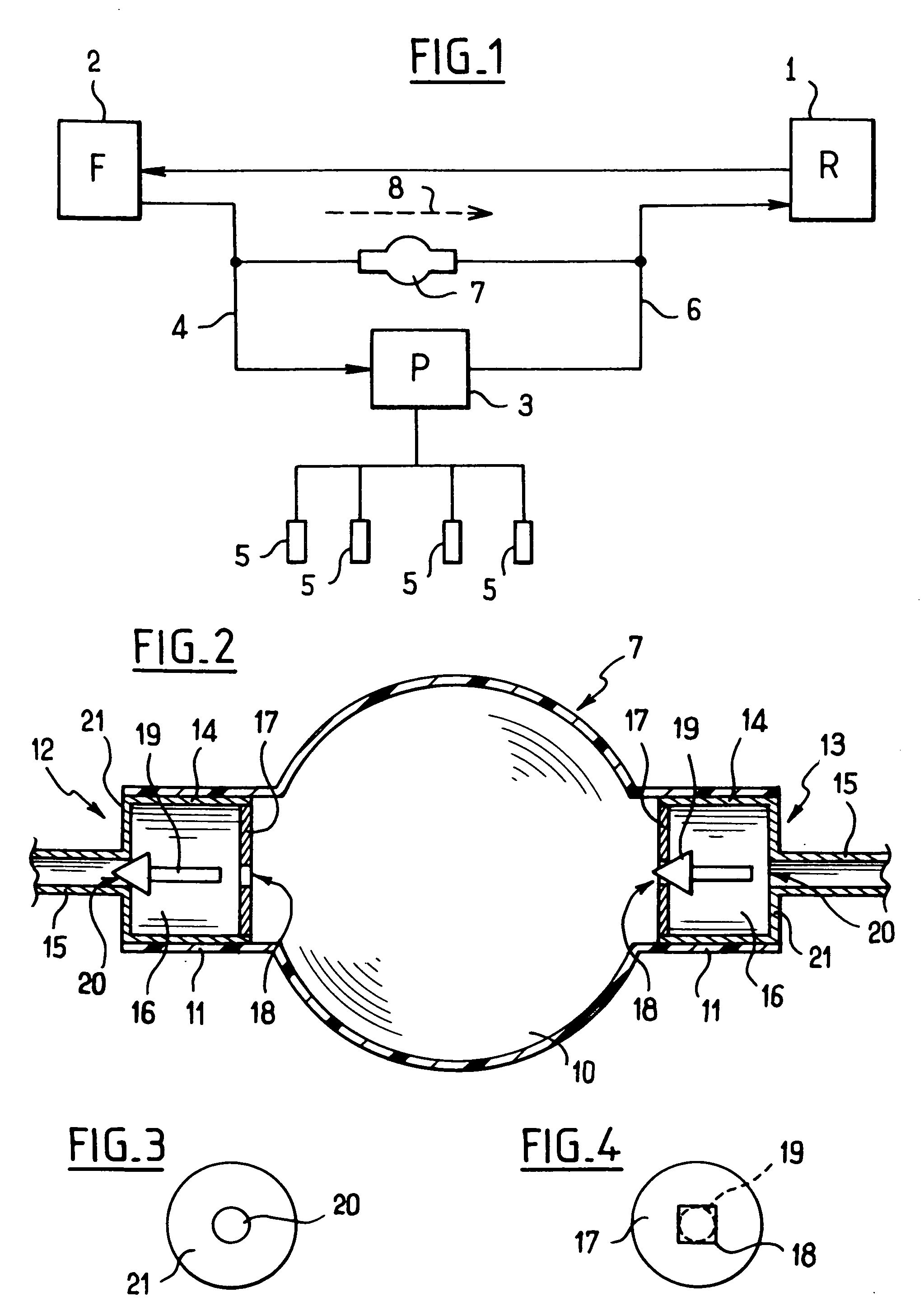
[0019] With reference to FIG. 2 and in conventional manner, the priming pump 7 comprises an elastomer envelope having a central zone 10 of large diameter that is manually deformable, the central zone 10 being associated with coupling zones 11 which extend from opposite sides thereof and which contain directional endpieces, specifically an inlet endpiece 12 and an outlet endpiece 13.

[0020] The inlet endpiece 12 and the outlet endpiece 13 both comprise a respective hollow body 14 engaged in the corresponding coupling zone 11 of the envelope. The hollow bodies 14 are extended by respective couplings 15 for connecting the priming pump to the circuit, the coupling 15 opening out via an orifice 20 into one of the end walls 21 of the hollow body 14. The hollow bodies 14 form respective cavities 16 that are defined between the end walls 12, and respective covers 17 that are fitted thereto and that present respective orifices 18.

[0021] In each of the endpieces 12, 13, a valve member 19 is ...


PUM


Abstract

The invention provides a priming pump comprising a deformable envelope associated with an inlet endpiece and an outlet endpiece each fitted with a moving valve member, the endpieces being arranged in such a manner that when the valve members are in the closed position, the outlet endpiece presents a leakage rate that is greater than the leakage rate of the inlet endpiece.

Description

[0001] The invention relates to a priming pump for a circuit subjecting said pump to an outlet pressure greater than an inlet pressure, intended in particular for mounting in parallel with a fuel circuit in certain vehicles, for example vehicles fitted with engines having a common injector manifold. BACKGROUND OF THE INVENTION [0002] In this type of configuration, shown in FIG. 1 which is a diagram of a fuel circuit, the fuel initially contained in a tank 1 passes through a filter 2, and is then drawn into an injector pump 3 by means of a feed line 4. The outlet from the injector pump 3 is connected to injectors 5 for feeding the cylinders of the engine, and excess fuel is returned to the tank 1 by means of a return line 6. [0003] The return line 6 is at a pressure greater than the pressure that exists in the tank 1, while the feed line 4 is at a pressure that is lower than the pressure in the tank 1. [0004] A priming pump 7 is disposed between the feed line 4 and the return line 6 ...

Claims


Application Information

Patent Timeline
IPC IPC(8): A61M1/00F04B23/00
CPCF04B49/225Y10T137/7848
Inventor PROUST, NATHALIE
Owner PROUST NATHALIE
Why Eureka
Try Eureka