
Photonic integrated circuit edge coupler structure with reduced reflection for integrated laser diodes

a technology of integrated laser diodes and couplers, which is applied in the field of coupling laser beams, can solve the problems of reducing the intensity of light usable for lidar purposes, reducing the linewidth and single frequency operation of lasers, and reducing the width of inner waveguides. the effect of reducing the width of the inner waveguide and optimizing the light coupling

Inactive Publication Date: 2019-01-17
GM GLOBAL TECH OPERATIONS LLC
View PDF1 Cites 8 Cited by
  • Summary
  • Abstract
  • Description
  • Claims
  • Application Information

AI Technical Summary

Benefits of technology

The patent describes a chip-based LIDAR system that includes a photonic chip with a laser that generates light. The light passes through several systems in the chip and is reflected back at the edge of the chip. This reflection is problematic because it can degrade the performance of the laser. To solve this problem, the patent proposes using an edge coupler with a designed angle that reduces the amount of reflection and maintains the intensity of light for LIDAR use. Additionally, the patent proposes using an inner and outer waveguide to transmit the light to the chip, with a tapering section in the inner waveguide to further minimize reflection and optimize the coupling of light with the chip. This solution improves the performance of the LIDAR system.

Problems solved by technology

However, light can be back-reflected at the edge coupler, which can degrade the linewidth and single frequency operation of the laser.
In addition, such back-reflection reduces the intensity of light usable for LIDAR purposes.

Method used


Image

  • Photonic integrated circuit edge coupler structure with reduced reflection for integrated laser diodes
  • Photonic integrated circuit edge coupler structure with reduced reflection for integrated laser diodes
  • Photonic integrated circuit edge coupler structure with reduced reflection for integrated laser diodes

Examples


Embodiment Construction

[0015]The following description is merely exemplary in nature and is not intended to limit the present disclosure, its application or uses. It should be understood that throughout the drawings, corresponding reference numerals indicate like or corresponding parts and features.

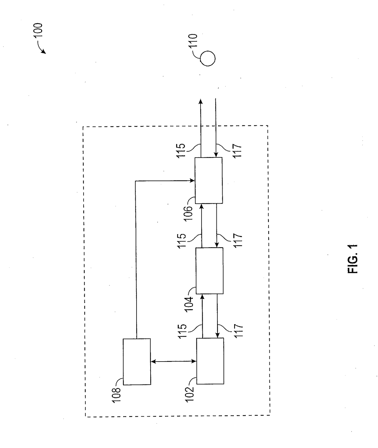
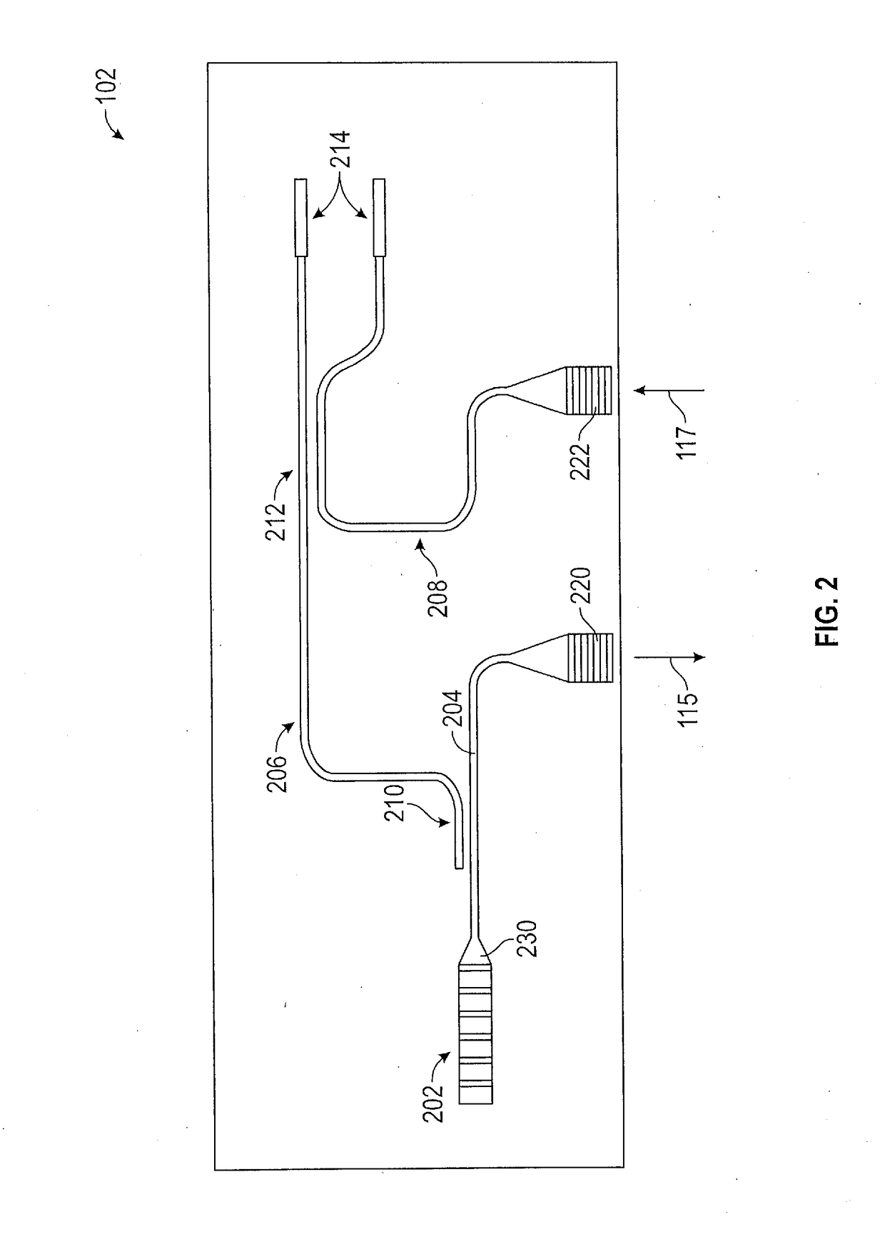
[0016]In accordance with an exemplary embodiment, FIG. 1 shows a schematic diagram of a LIDAR system 100. The LIDAR system 100 includes a photonic chip 102, an optical coupler 104, and a microelectromechanical system (MEMS) scanner 106. A processor 108 controls operation of the photonic chip 102 in order to perform operations of the LIDAR system 100. In various embodiments, the LIDAR system 100 are disposed on a semiconductor integrated chip residing on a printed circuit board. As discussed in further detail with respect to FIG. 2, the photonic chip 102 includes a light source, such as a laser, an optical waveguiding network and a set of photodiodes. The laser generates a transmitted light beam 115 that is tran...


PUM


Abstract

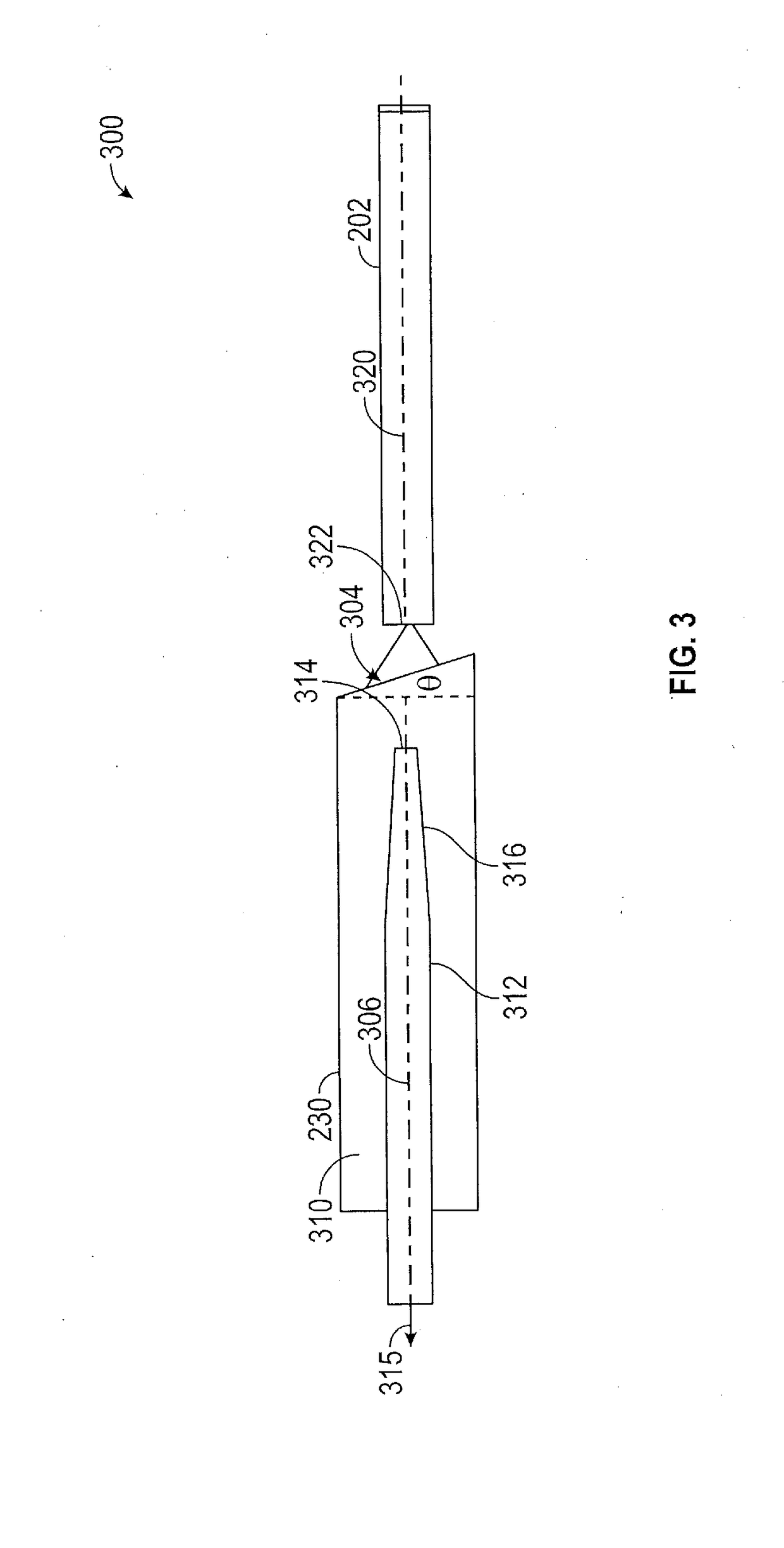
A photonic chip, an edge coupler for an integrated photonic system and a method for coupling a laser to the photonic chip. The edge coupler includes a waveguide of the photonic system having a longitudinal axis. The longitudinal axis of a waveguide of the photonic chip is aligned with a longitudinal axis of the laser. The facet of the waveguide facing the laser is at a non-perpendicular angle with respect to the longitudinal axis. Light is transmitted from the laser into the waveguide via the angled facet.

Description

CROSS-REFERENCE TO RELATED APPLICATIONS[0001]This application claims the benefit of priority of U.S. Provisional Application No. 62 / 531,414 filed Jul. 12, 2017, the disclosure of which is incorporated herein by reference in its entirety.INTRODUCTION[0002]The subject disclosure relates to a method and apparatus for of coupling a laser beam to a photonic chip and, in particular, to reducing back-reflection at a coupling between the laser beam and the photonic chip.[0003]A chip-based LIDAR (Light Detection and Ranging) system includes a photonic chip that uses a laser to generate light. Light from the laser enters into the photonic chip in order to pass through various systems of the photonic chip. An edge coupler is used to receive the light from the laser. However, light can be back-reflected at the edge coupler, which can degrade the linewidth and single frequency operation of the laser. In addition, such back-reflection reduces the intensity of light usable for LIDAR purposes. Acco...

Claims


Application Information

Patent Timeline
IPC IPC(8): G02B6/35G02B6/122G01S17/02G01S7/491G01S7/481G01S7/4911G01S7/4913G01S7/4914G01S17/32G01S17/34G01S17/86G01S17/931
CPCG01S7/4817G02B27/28G01S17/42G01S7/4815G01S7/4911G01S17/58G01S7/4816G01S17/34G01S17/931G01S17/86G01S7/499G01S17/02G02B6/122G02B6/2766G02B6/4209G02B2006/0098H01L23/544H01L31/02327H01L31/16H01L2223/54426H01L2223/54486G01S17/003G01S17/32G01S7/4914G01S7/491G01S7/4972B81B7/02B81B2207/03G01S7/4818G02B27/30H01S5/125G01S7/4913
Inventor SAYYAH, KEYVANEFIMOV, OLEGPATTERSON, PAMELA R.SARKISSIAN, RAYMONDHUANG, BIQIN
Owner GM GLOBAL TECH OPERATIONS LLC
Learn More