Device and method for the reconfiguration of a rechargeable energy storage device into separate battery connection strings
battery connection technology, applied in parallel/serial switching, indicating/monitoring circuits, transportation and packaging, etc., can solve the problem of less torque available above the nominal speed, reduce the usefulness of a rechargeable energy storage device, and thus limit the usable battery capacity to 6 kwh. the effect of extension
- Summary
- Abstract
- Description
- Claims
- Application Information
AI Technical Summary
Benefits of technology
Problems solved by technology
Method used
Image
Examples
first embodiment
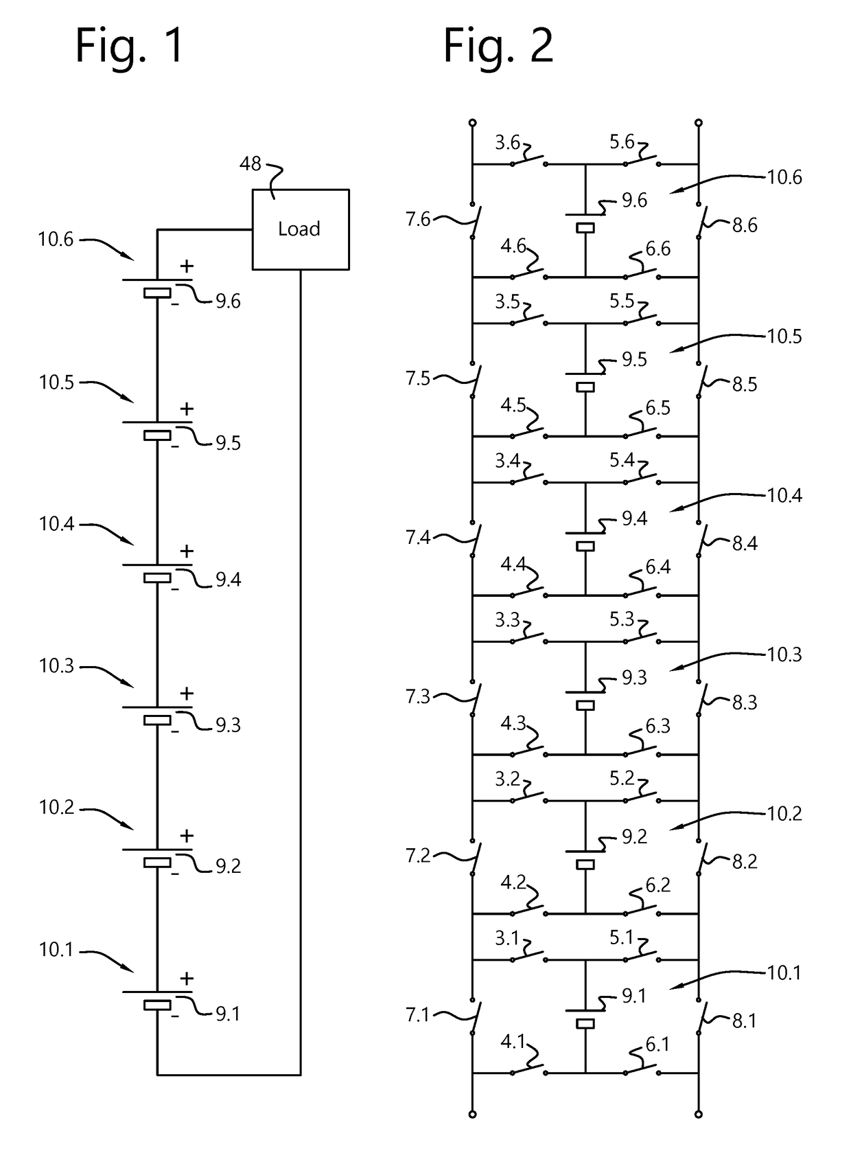
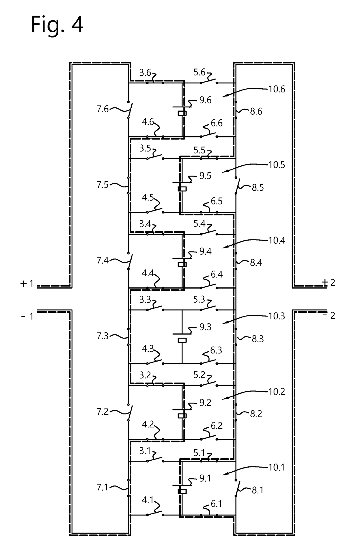
[0090]In this embodiment of the present invention a battery system is provided (as an example of a rechargeable energy system) to allow a reconfiguration of a battery pack into two or more new battery subpacks comprising “connection strings”. Each battery pack or subpack includes battery modules 10. The battery modules 10 are arranged in a ladder circuit with switches. In this embodiment, each rung of the ladder circuit comprises wires linking two switches in series between two connection strings. Between every other pair of rungs of the ladder circuit, one or more battery cells 9 are connected in a battery module 10. In each string, one bypass switch 5, 8 is connected in parallel with the one or more battery cells 9 of that module 10. In each battery module 10, which can include one or more battery cells 9, there is arranged a network of banks of switches. A first bank of switches is arranged to connect a battery module 10 in a first series connection with other battery modules 10....
second embodiment
[0101]This embodiment of the present invention allows a rechargeable energy storage system such as a battery pack to be subdivided into different subpacks comprising connection strings −1+1 and −2+2 having separate terminals, to be connected to different dc-dc converters, as shown schematically in FIG. 5. The system of FIG. 5 includes the ladder network, modules 10.1-10.6, the switches 3-8 and the energy storage cells 9.1-9.6 as previously described and in addition two dc-dc converters 44 and 46 that can be connected to a load 48.
[0102]The system of FIG. 5 allows the different rechargeable energy storage devices such as battery subpacks to supply power to the same load 48 although the voltage provided by the rechargeable energy storage devices comprising one or more strings −1+1, −2+2 is / are too low. For example, for each connection string −1+1, −2+2 there can be a dc-dc converter 44, 46 respectively connected thereto, whereby each dc-dc converter 44, 46 is connected to the same loa...
third embodiment
[0118]Configuration of a battery according to embodiments of the present invention does not necessarily have to be static. In FIG. 10, modules 10.1 to 10.3 retain a high capacity, while modules 10.4 to 10.6 only have a reduced capacity. FIG. 10 illustrates the ladder network, modules 10.1-10.6, the switches 3-8 and the energy storage cells 9.1-9.6 as previously described with the exception that modules 10.4 to 10.6 differ from modules 10.1 to 10.3 as to capacity. There is one dc-dc converter 44 and one load 48.
[0119]At first all modules 10.1 to 10.6 are put into a series connection string −1+1 (as shown) and operated in discharge until the modules 10.4 to 10.6 with the reduced capacity have reached their minimum SoC. Even if e.g. one module reaches its minimum SoC first, this module can be bypassed to allow the series connection of all other modules.
[0120]Once modules 10.4 to 10.6 are depleted, the remaining modules 10.1 to 10.3 can remain connected to the available dc-dc converter ...
PUM
 Abstract
Description
Claims
Application Information
 - R&D
- Intellectual Property
- Life Sciences
- Materials
- Tech Scout
- Unparalleled Data Quality
- Higher Quality Content
- 60% Fewer Hallucinations
Browse by: Latest US Patents, China's latest patents, Technical Efficacy Thesaurus, Application Domain, Technology Topic, Popular Technical Reports.
© 2025 PatSnap. All rights reserved.Legal|Privacy policy|Modern Slavery Act Transparency Statement|Sitemap|About US| Contact US: help@patsnap.com


