
Bioprinter temperature control system and bioprinter

a bioprinter and temperature control technology, applied in the field of bioprinters, can solve the problems of poor fluidity of the flow channel, affecting the survival rate of the biological material, so as to achieve the effect of solving the current problem, improving the survival rate of the printing material, and uniform temperature control

Active Publication Date: 2019-01-10
SICHUAN REVOTEK CO LTD
View PDF0 Cites 6 Cited by
  • Summary
  • Abstract
  • Description
  • Claims
  • Application Information

AI Technical Summary

Benefits of technology

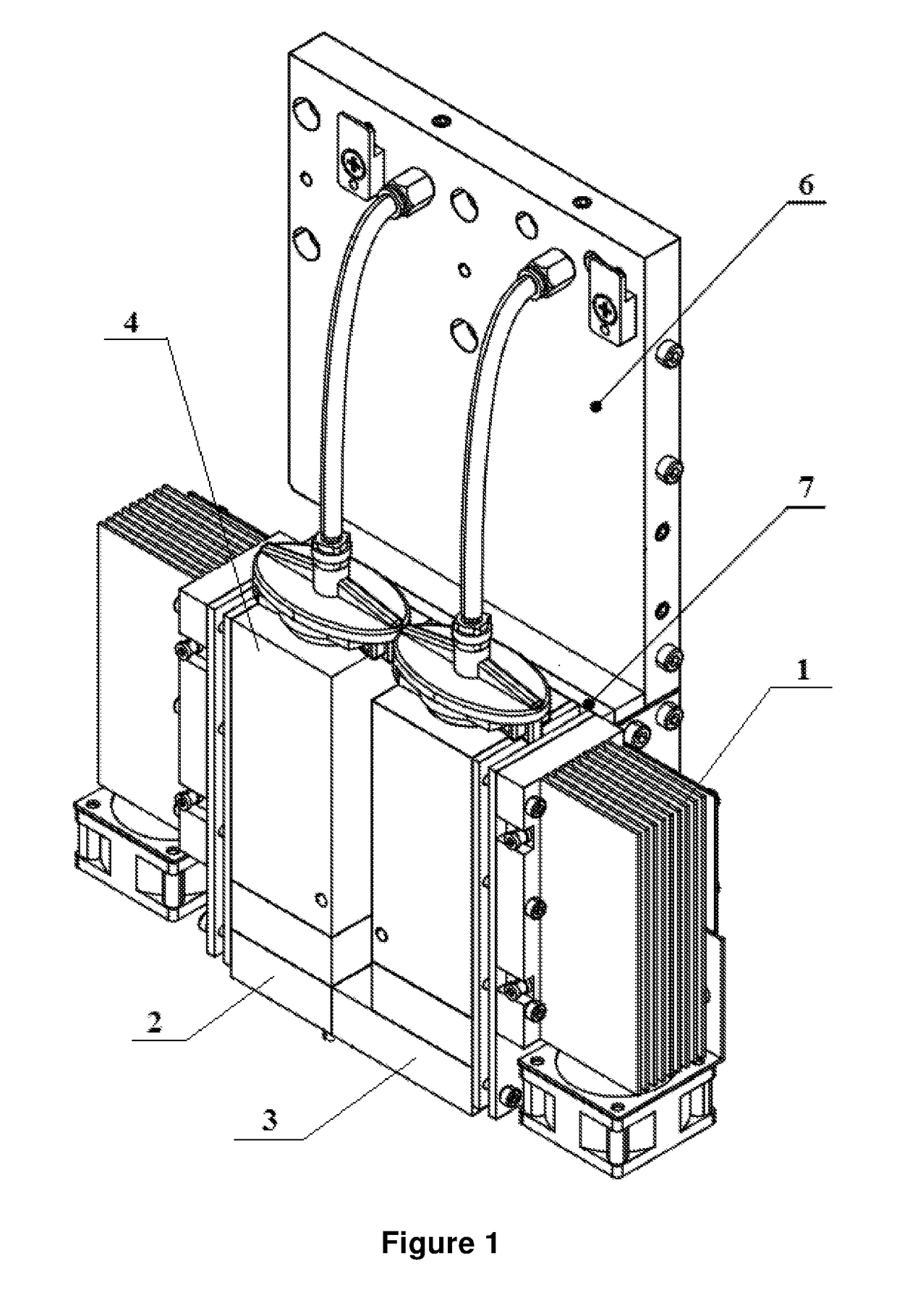
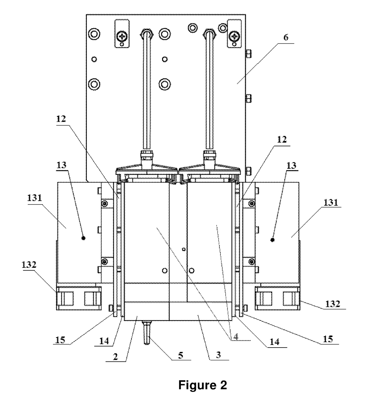
The present invention provides a bioprinter temperature control system to improve printing efficiency and prevent clogging of printing material. The system includes a flow channel temperature control system to control the temperature between the bioprinting material container and the nozzle, and a heat equalizing plate to ensure uniform temperature control of the container and improve the survival rate of the printing material. Additionally, a nozzle temperature control system is provided to prevent clogging at the nozzle and improve printing efficiency, especially when a longer nozzle is used. Overall, the system provides a more desirable printing environment for cells and ensures the biological function of the printed material.

Problems solved by technology

One technical problem to be solved by the present invention is that: the existing bioprinter temperature control system does not perform temperature control on the biological material in the flow channel from the bioprinting container to the nozzle, resulting in the clogging of the biological material with poor fluidity in the flow channel.
Moreover, as the temperature of the biological material in the flow channel is not controlled, risks such as a low survival rate and a degradation in the biological function of the biological material occur.

Method used


Image

  • Bioprinter temperature control system and bioprinter
  • Bioprinter temperature control system and bioprinter
  • Bioprinter temperature control system and bioprinter

Examples


Embodiment Construction

[0042]Thereinafter, the technical solution in the embodiments of the present invention will be explicitly and completely described in combination in combination with the drawings in the embodiments of the present invention. Apparently, the described embodiments are merely part of the embodiments of the present invention, rather than all the embodiments. The following descriptions of at least one exemplary embodiment which are in fact merely descriptive, by no means serve as any delimitation on the present invention as well as its application or use. On the basis of the embodiments of the present invention, all the other embodiments acquired by a person skilled in the art on the premise that no inventive effort is involved fall into the protection scope of the present invention.

[0043]In the description of the present invention, it is necessary to understand that, the azimuth or positional relations indicated by such azimuth terms as “front, rear, up, down, left, right”, “transverse, ...


PUM

PropertyMeasurementUnit
temperatureaaaaaaaaaa
heat insulatingaaaaaaaaaa
TEMPERATUREaaaaaaaaaa

Abstract

The present invention relates to the technical field of a bioprinter, and in particular relates to a bioprinter temperature control system and a bioprinter. The bioprinter temperature control system provided by the present invention, comprises a flow channel temperature control system, for controlling a temperature of a flow channel between an outlet of a bioprinting material container of a bioprinter and a nozzle of the bioprinter, such that the temperature of the flow channel conforms to a desired temperature of a biological printing material. The temperature control system of the present invention can realize the temperature control of the biological printing material, improving the survival rate of the printing material, and ensuring the biological function of the printing material.

Description

RELATED APPLICATION[0001]This Application is a national stage filing under 35 U.S.C. 371 of International Patent Application Serial No. PCT / CN2015 / 099870, filed Dec. 30, 2015, entitled “BIOPRINTER TEMPERATURE CONTROL SYSTEM AND BIOPRINTER”. The entire contents of these applications are incorporated herein by reference in their entirety.TECHNICAL FIELD[0002]The present invention relates to the technical field of a bioprinter, and in particular relates to a bioprinter temperature control system and a bioprinter.BACKGROUND ART[0003]3D bioprinting refers to a technology of printing biological materials (including natural biological materials and synthetic biological materials or cellular solutions) into a designed three-dimensional structure based on 3D printing principles and methods. Since the printing material of the 3D bioprinting is biological material, compared with the ordinary 3D printing technology, one characteristic of the bioprinter lies in that it needs to provide the print...

Claims


Application Information

Patent Timeline
Patent Type & Authority Applications(United States)
IPC IPC(8): B29C64/393B29C64/295B33Y30/00B33Y40/00B29C64/209B33Y50/02B29C64/255G05D23/30
CPCB29C64/393B29C64/295B33Y30/00B33Y40/00F25B21/04B33Y50/02B29C64/255G05D23/30B29C64/209B29C35/0288C12M33/00B29C64/321
Inventor WANG, DEMINGWEN, XUEMINLI, YIJUNZHANG, LEQING
Owner SICHUAN REVOTEK CO LTD
Learn More