
Battery with Acidified Cathode and Lithium Anode

Active Publication Date: 2018-11-22
HHELI LLC
View PDF2 Cites 11 Cited by
  • Summary
  • Abstract
  • Description
  • Claims
  • Application Information

AI Technical Summary

Benefits of technology

This patent describes a new material called acidified metal oxides (AMO) that can be used in batteries, catalysts, sensors, and other applications. By combining AMOs with acidic species, they can improve the performance and longevity of devices. The use of acidic electrodes or electrodes containing acidic species can enhance the capacity, cyclability, and longevity of batteries, particularly when used in combination with AMO materials. The pH of the electrodes can be adjusted to improve the performance of batteries. Overall, this new material and technique can provide better performance and longer life for batteries and related devices.

Problems solved by technology

The mechanisms by which the surface controls reactivity, however, are not always well characterized or understood.
Superacidity may, for example, degrade system components or catalyze unwanted side reactions.
The battery literature teaches that acidic groups are detrimental in batteries, where they can attack metal current collectors and housings and cause deterioration in other electrode components.
Further, the prior art teaches that an active, catalytic electrode surface leads to electrolyte decomposition which can result in gas generation within the cell and ultimately in cell failure.

Method used


Image

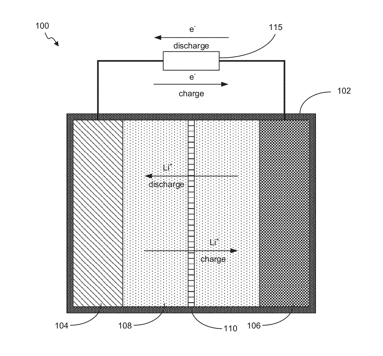
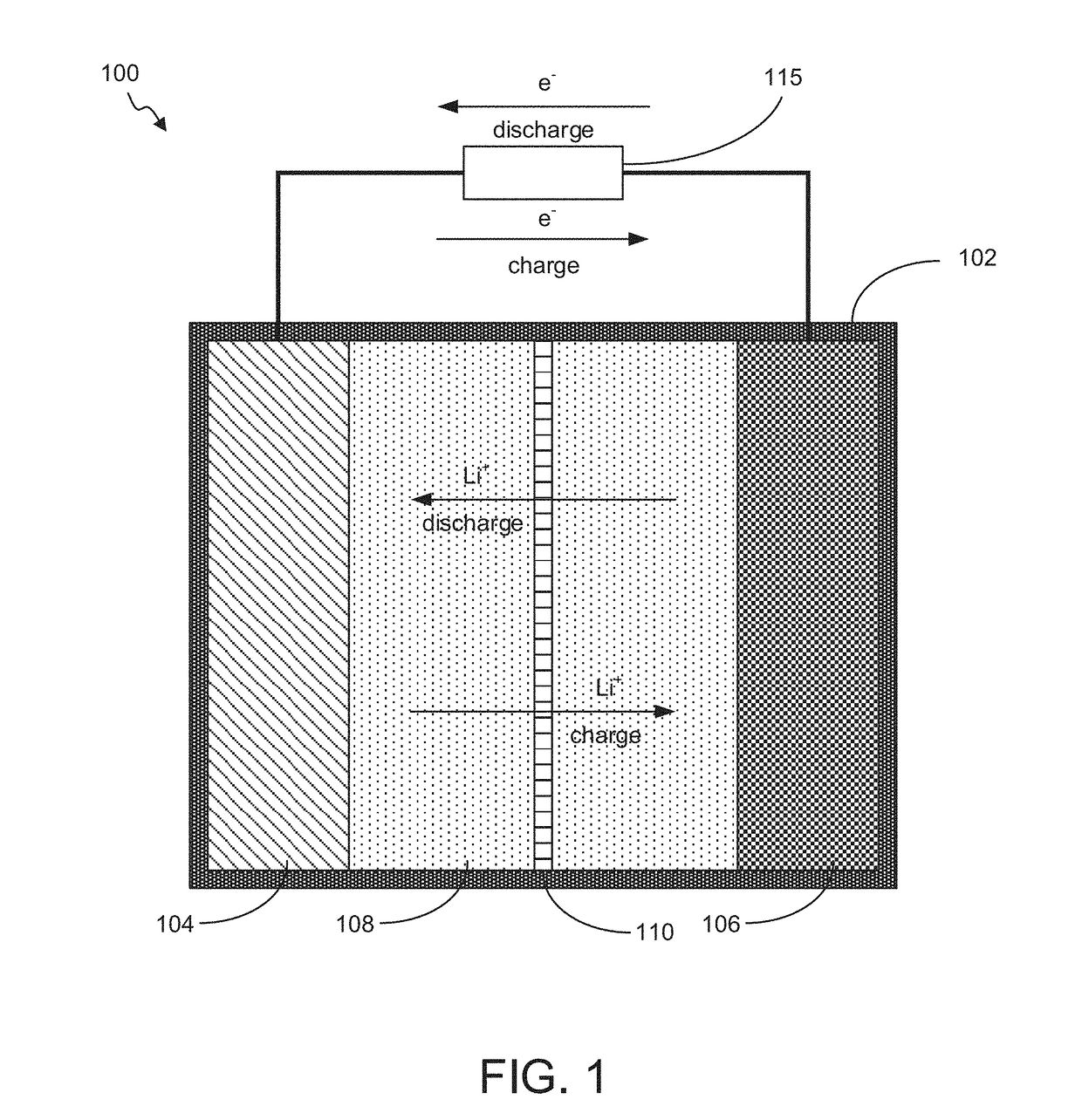
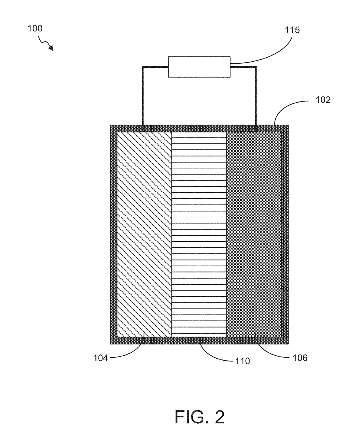
  • Battery with Acidified Cathode and Lithium Anode
  • Battery with Acidified Cathode and Lithium Anode
  • Battery with Acidified Cathode and Lithium Anode

Examples


example 1

AMO of Tin Oxide Functionalized by Acetate / Chloride

[0177]A tin oxide AMO was synthesized using a single-pot hydrothermal synthesis method. Briefly, tin acetate (Sn(CH3COO)2) was dissolved in an ethanol / water solution and acidified by addition of hydrochloric acid (HCl). The resultant AMO nanomaterial was a soft, grey material and was formed into an electrode. The electrode was assembled in a battery cell against lithium metal and cycled by discharging to zero volts, followed by charging to 1.5 volts. FIG. 16 depicts a plot of the measured capacity versus cycle number, as well as a plot of the voltage as a function of time during cycling.

example 2

AMO of Tin Oxide Functionalized by Acetate / Sulfate

[0178]A tin oxide AMO was synthesized using a single-pot hydrothermal synthesis method. Briefly, tin acetate (Sn(CH3COO)2) was dissolved in an ethanol / water solution and acidified by addition of sulfuric acid (H2SO4). The resultant AMO nanomaterial was a grey, flaky material and was formed into an electrode. The electrode was assembled in a battery cell against lithium metal and cycled by discharging to zero volts, followed by charging to 1.5 volts. FIG. 17 depicts an electron micrograph image of the AMO nanomaterial, a plot of the measured capacity versus cycle number, as well as a plot of the voltage as a function of time during cycling.

example 3

AMO of Tin Oxide Functionalized By Acetate / Nitrate

[0179]A tin oxide AMO was synthesized using a single-pot hydrothermal synthesis method. Briefly, tin acetate (Sn(CH3COO)2) was dissolved in an ethanol / water solution and acidified by addition of nitric acid (HNO3). The resultant AMO nanomaterial was a grey, flaky material and was formed into an electrode. The electrode was assembled in a battery cell against lithium metal and cycled by discharging to zero volts, followed by charging to 1.5 volts. FIG. 18 depicts an electron micrograph image of the AMO nanomaterial, a plot of the measured capacity versus cycle number, as well as a plot of the voltage as a function of time during cycling.


PUM


Abstract

A battery comprising an acidified metal oxide (“AMO”) material, preferably in monodisperse nanoparticulate form 20 nm or less in size, having a pH<7 when suspended in a 5 wt % aqueous solution and a Hammett function H0>−12, at least on its surface.

Description

CROSS-REFERENCE To RELATED CASE[0001]This application claims the benefit of U.S. provisional patent application Ser. No. 62 / 507,659, filed on May 17, 2017, entitled “Battery with Acidified Cathode and Lithium Anode,” and incorporates such provisional application by reference into this disclosure as if fully set out at this point.FIELD[0002]This disclosure is in the field of materials useful in chemical energy storage and power devices such as, but not limited to, batteries. More specifically, this disclosure relates to a battery cell with a cathode and / or an anode comprising acidified metal oxide (“AMO”) nanomaterials. In some embodiments, a battery cell is constructed with an AMO cathode and an anode consisting substantially of elemental lithium.BACKGROUND OF THE INVENTION[0003]Metal oxides are compounds in which oxygen is bonded to metal, having a general formula MmOx. They are found in nature but can be artificially synthesized. In synthetic metal oxides the method of synthesis c...

Claims


Application Information

Patent Timeline
IPC IPC(8): H01M4/525H01M10/0525H01M4/38H01M4/505
CPCH01M4/382H01M4/525H01M2004/021H01M2004/028H01M4/505H01M10/0525C01G19/02C01G23/047C01G25/02C01G29/00C01G30/005C01G49/0027C01G49/02C01G15/00H01M4/366H01M4/483H01M4/523H01M4/62H01M10/052H01M10/058C01P2002/50C01P2002/85C01P2004/03C01P2006/40Y02P70/50Y02E60/10H01M4/387H01M4/48
Inventor JOHNSON, PAIGE L.
Owner HHELI LLC
Learn More