
Method of producing wear-resistant iron-based sintered alloy

Inactive Publication Date: 2018-10-04
TOYOTA JIDOSHA KK +1
View PDF3 Cites 2 Cited by
  • Summary
  • Abstract
  • Description
  • Claims
  • Application Information

AI Technical Summary

Benefits of technology

The present disclosure provides a method for making a wear-resistant iron-based sintered alloy that can be easily machined without getting stuck. The inventors found that adding molybdenum and molybdenum carbide to the alloy can prevent the iron matrix from getting plastically deformed and cause adhesive wear. By oxidizing some of the iron in the alloy to triiron tetraoxide, its wear resistance is improved without compromising its machinability. Overall, this method allows for improved wear resistance while still being able to machine the alloy easily.

Problems solved by technology

Therefore, when the wear-resistant iron-based sintered alloy and a metallic material of a sliding counterpart component that comes in contact therewith are in metal-contact with each other, a contact surface of the wear-resistant iron-based sintered alloy is likely to be plastically deformed and adhesive wear easily occurs on the contact surface.
However, there is a risk of the machinability of the wear-resistant iron-based sintered alloy deteriorating accordingly and it is difficult to achieve both adhesive wear resistance and machinability.

Method used


Image

  • Method of producing wear-resistant iron-based sintered alloy
  • Method of producing wear-resistant iron-based sintered alloy
  • Method of producing wear-resistant iron-based sintered alloy

Examples


example 1

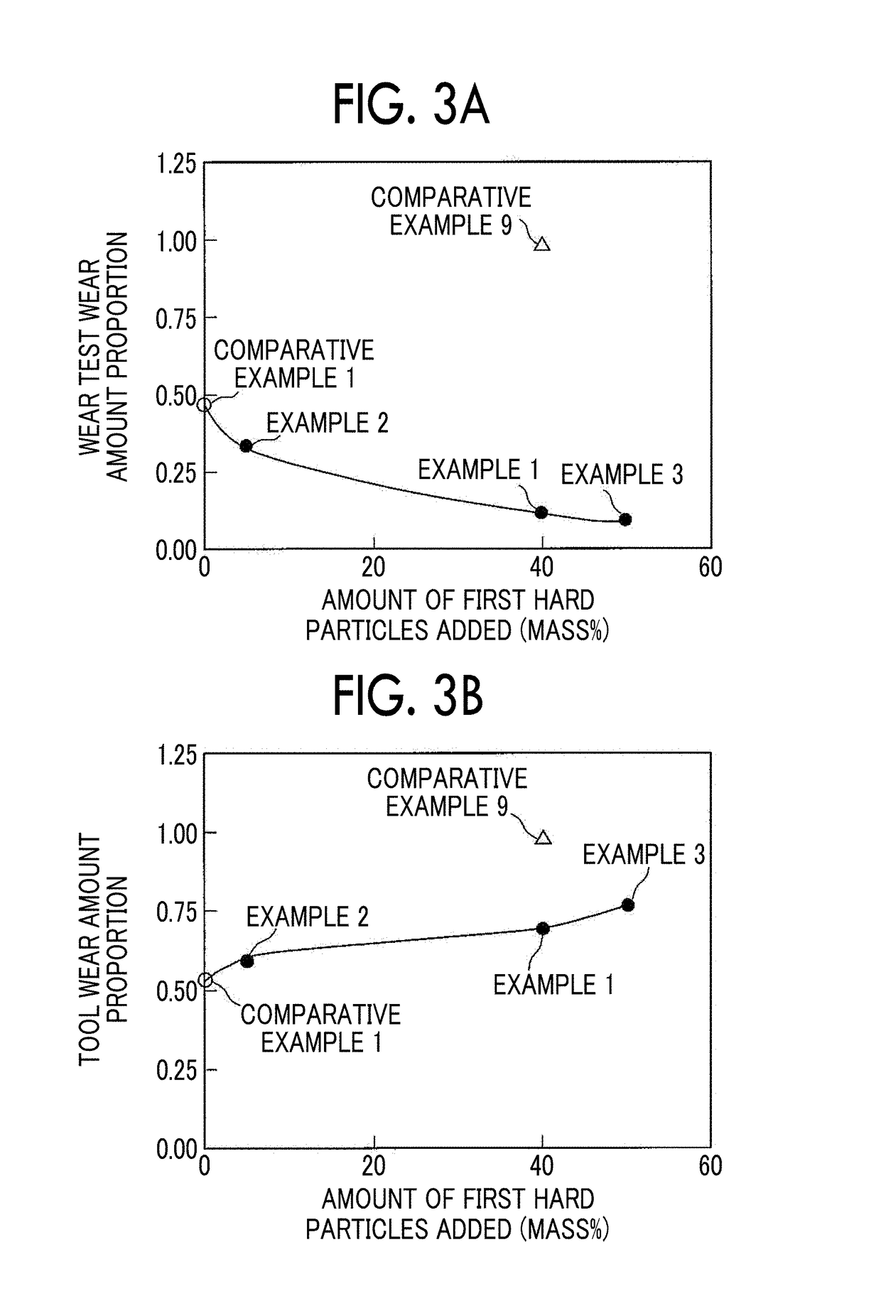
Optimal Amount of First Hard Particles Added

[0098]A sintered alloy according to Example 1 was produced according to the following production method. As the first hard particles, hard particles (commercially available from Daido Steel Co., Ltd) produced from an alloy including Mo: 40 mass %, Ni: 30 mass %, Co: 20 mass %, Mn: 5 mass %, Si: 0.8 mass %, and C: 1.2 mass %, with the balance including Fe and inevitable impurities (that is, Fe-40Mo-30Ni-20Co-5Mn-0.8Si-1.2C) using a gas atomizing method were prepared. The first hard particles were classified into a range of 44 μm to 250 μm using a sieve according to JIS standard Z8801. Here, “granularity of particles” in this specification is a value obtained by classification according to this method.

[0099]As the second hard particles, second hard particles (commercially available from Kinsay Matec Co., Ltd) produced from an Fe-65 alloy including Mo: 65 mass %, with the balance including Fe and inevitable impurities using a grinding method ...

examples 2 and 3

Optimal Amount of First Hard Particles Added

[0102]In the same manner as in Example 1, sintered alloy test pieces were prepared. Examples 2 and 3 were examples for evaluating an optimal amount of first hard particles added. Examples 2 and 3 differed from Example 1 in that, as shown in Table 1, the first hard particles were added at a proportion of 5 mass % and 50 mass %, respectively, with respect to the entire mixed powder.

examples 4 and 5

Optimal Amount of Second Hard Particles Added

[0103]In the same manner as in Example 1, sintered alloy test pieces were prepared. Examples 4 and 5 were examples for evaluating an optimal amount of second hard particles added. Examples 4 and 5 differed from Example 1 in that, as shown in Table 1, the second hard particles were added at a proportion of 1 mass % and 5 mass %, respectively, with respect to the entire mixed powder.


PUM

PropertyMeasurementUnit
Percent by massaaaaaaaaaa

Abstract

A wear-resistant iron-based sintered alloy made of a mixed powder including first hard particles, second hard particles, graphite particles, and iron particles is produced. The first hard particles are Fe—Mo—Ni—Co—Mn—Si—C alloy particles. The second hard particles are Fe—Mo—Si alloy particles. The mixed powder includes the first hard particles at 5 mass % to 50 mass %, the second hard particles at 1 mass % to 8 mass %, and the graphite particles at 0.5 mass % to 1.5 mass % when a total amount of the above particles is set as 100 mass %. In a sintering process, sintering is performed so that the hardness of the first hard particles becomes 400 to 600 Hv and the hardness of the second hard particles exceeds 600 Hv. Then, an oxidation treatment is performed so that a density difference between before and after the oxidation treatment in a sintered product becomes 0.05 g / cm3 or more.

Description

INCORPORATION BY REFERENCE[0001]The disclosure of Japanese Patent Application No. 2017-074255 filed on Apr. 4, 2017 including the specification, drawings and abstract is incorporated herein by reference in its entirety.BACKGROUND1. Technical Field[0002]The present disclosure relates to a method of producing a wear-resistant iron-based sintered alloy including hard particles suitable for improving wear resistance of a sintered alloy.2. Description of Related Art[0003]A sintered alloy based on iron may be applied to a valve seat and the like. Hard particles may be included in the sintered alloy in order to further improve wear resistance. When hard particles are included, graphite particles and iron particles are mixed into hard particles to form a powder, and the mixed powder is compact-molded into a molded product for a sintered alloy. Then, generally, the molded product for a sintered alloy is heated and thus it is sintered and becomes a sintered alloy.[0004]As a method of producin...

Claims


Application Information

Patent Timeline
IPC IPC(8): C22C33/02C22C38/12C22C38/10C22C38/04C22C38/02B22F3/16B22F5/10
CPCC22C33/0207C22C38/12C22C38/105C22C38/04C22C38/02B22F3/16B22F5/106B22F2301/35B22F2302/40B22F2201/05B22F2201/02C22C1/045C22C27/04C22C30/00C22C33/0285C22C38/08C22C38/10B22F2999/00B22F3/10B22F3/02B22F2201/10B22F2003/248B22F2009/0824F01L3/02F01L2301/00F01L2303/00C22C1/055
Inventor SHINOHARA, NOBUYUKIKAMO, YUKIUEDA, YOSHIHISAYONEDA, TAKANORINAKAMURA, TAKESHI
Owner TOYOTA JIDOSHA KK
Learn More