
Battery cell including electrode lead containing gas adsorbent

a battery cell and electrode lead technology, which is applied in the direction of batteries, other chemical processes, sustainable manufacturing/processing, etc., can solve the problems of large amount of gas generated, battery explosion, and high voltage in the battery

Active Publication Date: 2018-08-30
LG ENERGY SOLUTION LTD
View PDF3 Cites 6 Cited by
  • Summary
  • Abstract
  • Description
  • Claims
  • Application Information

AI Technical Summary

Benefits of technology

The present invention provides a method to improve stability and performance of a battery cell by coating a gas adsorbent on the tab connection part of an electrode lead. By increasing the coating area of the gas adsorbent and reinforcing mechanical rigidity of the connection portion between the electrode lead and electrode tab, the risk of battery case rupture and safety reduction due to gas discharge can be prevented. The use of chemically stable inorganic particles, with high ion conductivity, low density, and low permittivity, can further enhance the performance of the battery.

Problems solved by technology

For example, explosion of the battery may occur due to a high temperature and a high voltage in the battery which may be caused by an abnormal operation state of the battery cell, for example, an internal short-circuit of the battery cell, an overcharge state of the battery cell in which a current and voltage exceed an allowable current and voltage, exposure of the battery cell to a high temperature, deformation of the battery cell by dropping or external impacts, and the like.
Particularly, as one of the safety problems, when the internal short-circuit occurs in the battery cell due to exposure to a high temperature environment, malfunction, or the like, a decomposition reaction occurs in a cathode interface, and thus, a large amount of gas is generated.
As a result, the battery case is ruptured due to an increase in internal pressure, such that the gas is discharged to the outside of the battery cell.
Generally, this internal gas includes components toxic to human bodies such as carbon monoxide, and the like, thereby causing a safety problem.

Method used


Image

  • Battery cell including electrode lead containing gas adsorbent
  • Battery cell including electrode lead containing gas adsorbent
  • Battery cell including electrode lead containing gas adsorbent

Examples


Embodiment Construction

[0102]Hereinafter, the present invention will be described in more detail with reference to the accompanying drawings according to exemplary embodiments of the present invention, but the scope of the present invention is not limited thereto.

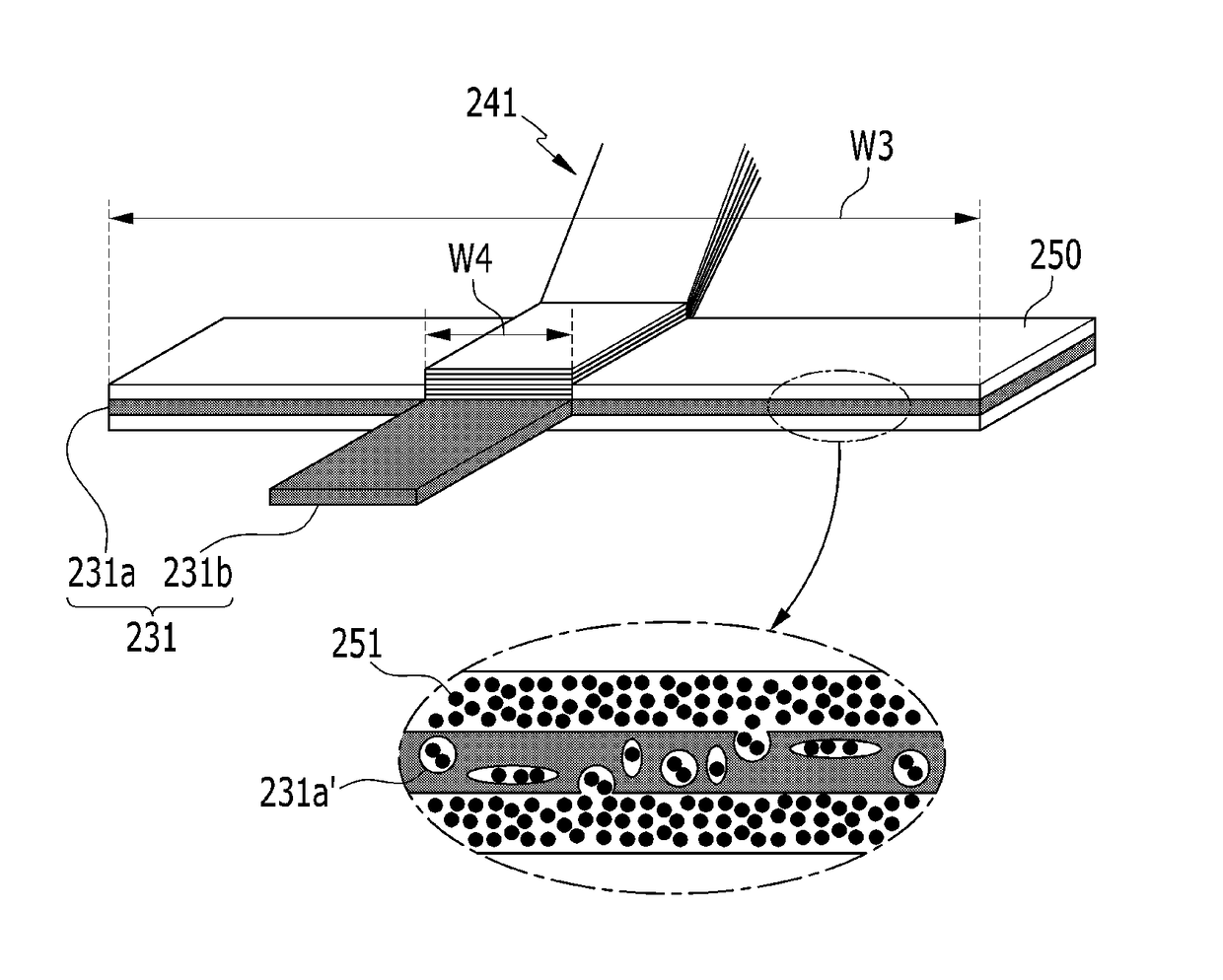
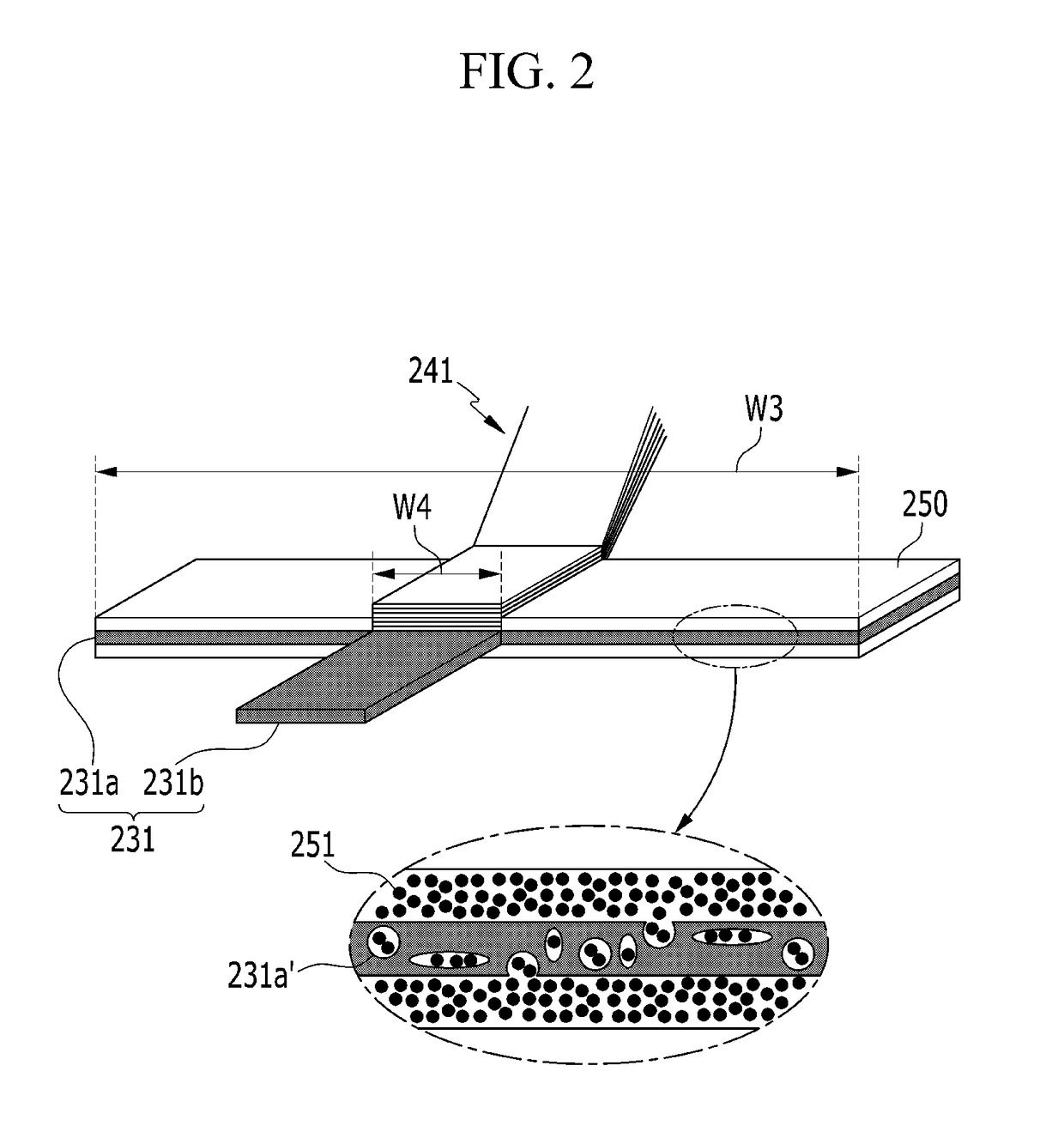
[0103]FIG. 2 is a mimetic view schematically illustrating structures of a cathode tab and a cathode lead of a battery cell according to an exemplary embodiment of the present invention.

[0104]Referring to FIG. 2, a cathode lead 231 includes a tab connection part 231a and a protrusion extension part.

[0105]The tab connection part 231a has a structure in which a width W3 thereof in a width direction perpendicular to a protrusion direction of a cathode tab 221 is relatively large as compared to a width W4 of the cathode tab 221, and the cathode tab 221 is bonded to a central portion of the tab connection part 231a by welding.

[0106]A gas adsorbent coating layer 250 is entirely formed on the remaining portions of upper and lower surfaces of the tab conn...


PUM

PropertyMeasurementUnit
Fractionaaaaaaaaaa
Lengthaaaaaaaaaa
Polarityaaaaaaaaaa

Abstract

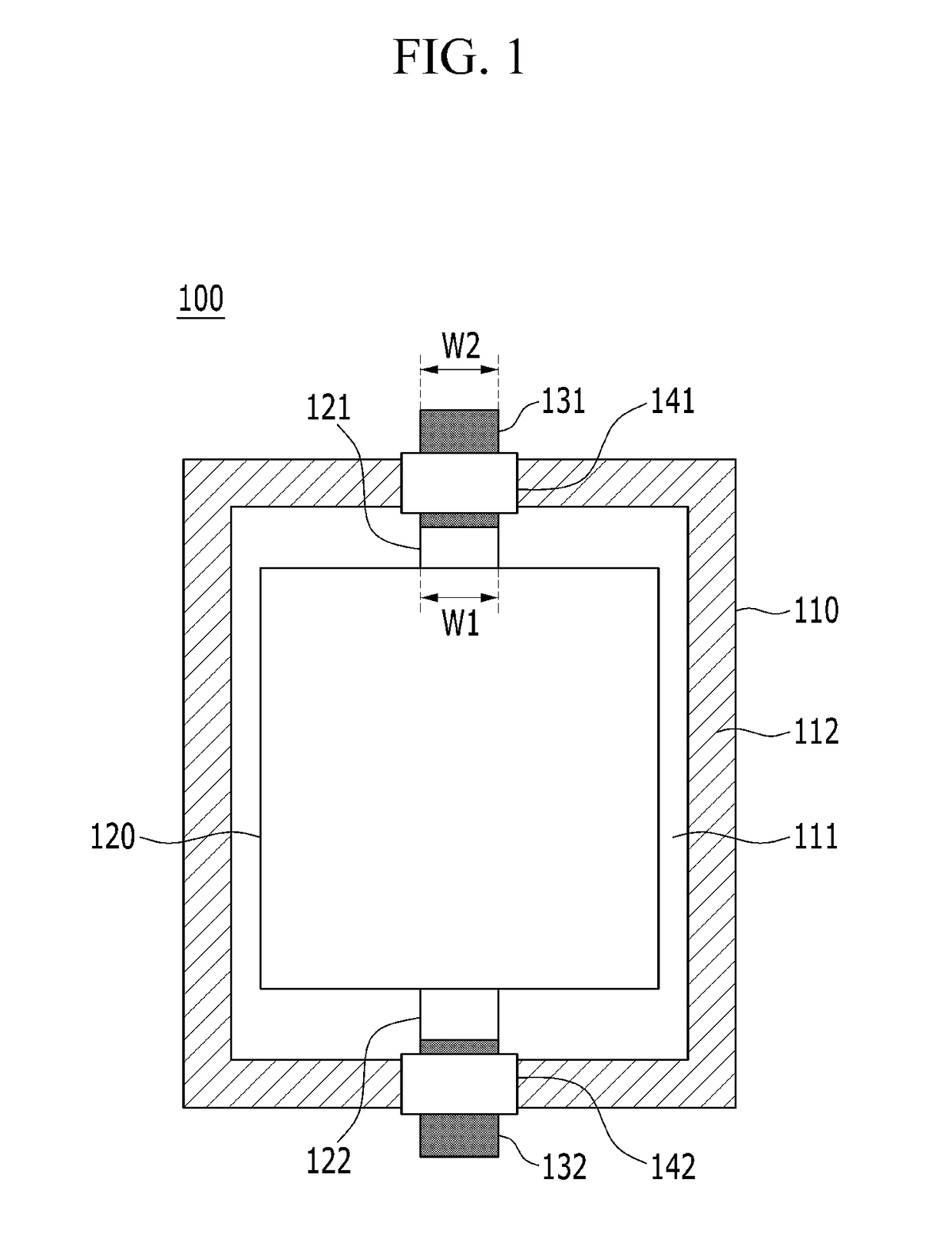
Disclosed herein is a battery cell including: an electrode assembly including an electrode tab protruding toward at least one outer periphery; a battery case including an accommodation part in which the electrode assembly is mounted; and an electrode lead connected to the electrode tab for electrical connection with an external device, wherein the electrode lead includes: a tab connection part electrically connected to the electrode tab; and a protrusion extension part extended from the tab connection part and protruding outwardly of the battery case to thereby be electrically connected to the external device, the tab connection part being coated with a gas adsorbent.

Description

CROSS-REFERENCE TO RELATED APPLICATION(S)[0001]This application claims priority to and the benefit of Korean Patent Application No. 10-2015-0175545 filed on Dec. 10, 2015 with the Korean Intellectual Property Office, the entire contents of which are incorporated herein by reference.TECHNICAL FIELD[0002]The present invention relates to a battery cell including an electrode lead containing a gas adsorbent.BACKGROUND ART[0003]Recently, in accordance with an increase in cost of an energy source due to exhaustion of fossil fuel and interest in environmental contamination, the demand for an eco-friendly alternative energy source has become an essential factor for future life. Therefore, research into various power generation technologies such as a nuclear power generation technology, a photovoltaic power generation technology, a wind power generation technology, a tidal power generation technology, and the like, has been continuously conducted, a power storage device for efficiently using...

Claims


Application Information

Patent Timeline
IPC IPC(8): H01M10/52B01J20/20B01J20/18H01M2/26H01M2/02H01M2/10H01M10/42H01M50/124H01M50/14H01M50/538
CPCH01M10/52B01J20/20B01J20/18H01M2/263H01M2/0275H01M2/1072H01M10/4235H01M2220/20H01M10/0525Y02E60/10H01M50/538Y02P70/50H01M50/14H01M50/124
Inventor KIM, YONG JUNKIM, SEOK KOOCHUNG, SEUNG HYUN
Owner LG ENERGY SOLUTION LTD
Learn More