
Pressure Sensor Arrangement and Measuring Transducer for Process Instrumentation Having Such a Pressure Sensor Arrangement

a technology of pressure sensor and measuring transducer, which is applied in the direction of instruments, rapid change measurement, measurement devices, etc., can solve the problems of difficult to achieve the required accuracy, unsatisfactory extent, and comparatively complex design of such a measuring cell, and achieves significant simple mechanical design, high long-term stability, and rugged design

Active Publication Date: 2018-08-30
SIEMENS AG
View PDF1 Cites 5 Cited by
  • Summary
  • Abstract
  • Description
  • Claims
  • Application Information

AI Technical Summary

Benefits of technology

The invention is a pressure sensor arrangement for measuring the rotation of a diaphragm in a tube. The arrangement has several advantages over existing pressure sensor arrangements. Firstly, the sensor's articulation is close to the tube wall, making it easy to measure the rotation externally. This simplifies the mechanical design of the arrangement compared to existing arrangements which require additional components like oil fill, overload protection, and pressure-resistant glass feedthrough. Secondly, the diaphragm is not subject to static pressure, reducing the risk of overload and providing a reliable and stable sensor. Interestingly, the diaphragm is thinner towards its edge, making it flex weaker, which allows for its mounting via a flexure bearing. The residual flexural strength of the diaphragm is also utilized to measure the rotation of the articulation on the outside of the tube as a surface strain. Additionally, the arrangement includes a recess in the outer wall of the tube, which further simplifies the measurement of the diaphragm deformation. This arrangement is highly sensitive for measuring diaphragm deformation and can be used as a measuring cell or detector in process instrumentation.

Problems solved by technology

The design of such a measuring cell is therefore comparatively complex and a large number of welding processes are required to manufacture the measuring cell.
However, in the case of the pressure sensor arrangement described, the differential pressure measurement is disadvantageously heavily dependent on the static pressure that particularly results in deformation of the sidewall diaphragm and compensation of which is only possible to an unsatisfactory extent, because this requires exact positioning of the strain gauges applied to the tube's outer wall that is in practice difficult to achieve with the required accuracy.

Method used


Image

  • Pressure Sensor Arrangement and Measuring Transducer for Process Instrumentation Having Such a Pressure Sensor Arrangement
  • Pressure Sensor Arrangement and Measuring Transducer for Process Instrumentation Having Such a Pressure Sensor Arrangement
  • Pressure Sensor Arrangement and Measuring Transducer for Process Instrumentation Having Such a Pressure Sensor Arrangement

Examples


Embodiment Construction

[0018]Identical parts are provided with the same reference characters in the figures.

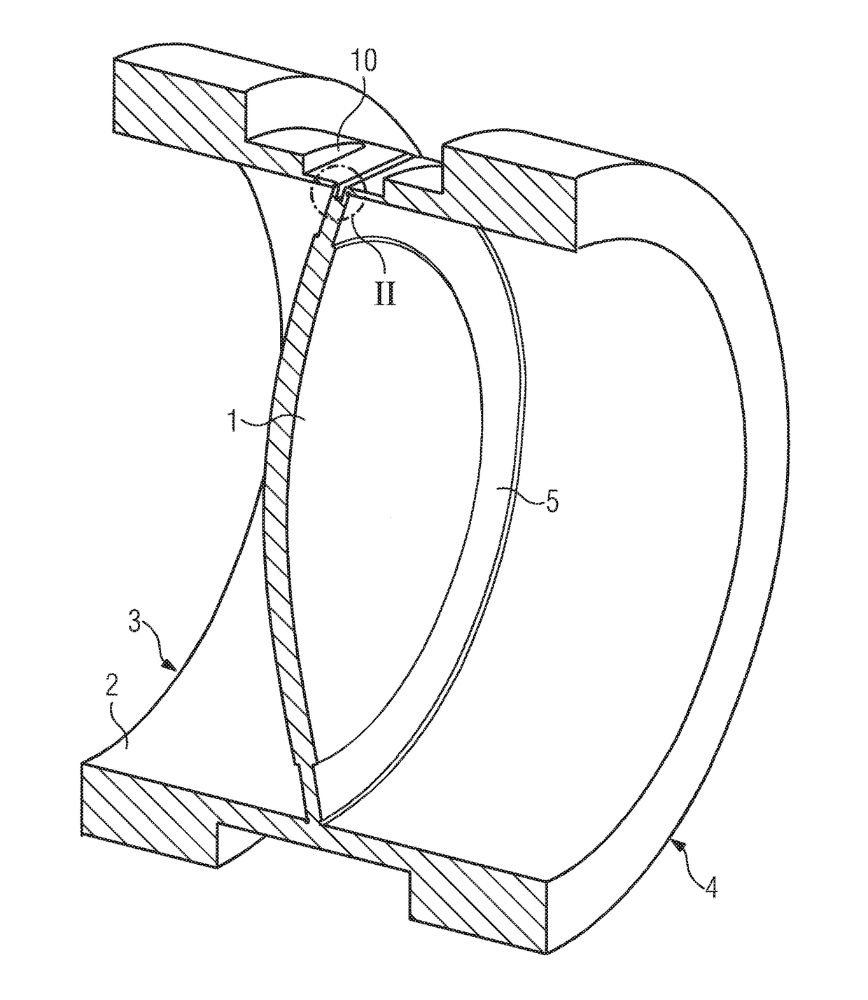
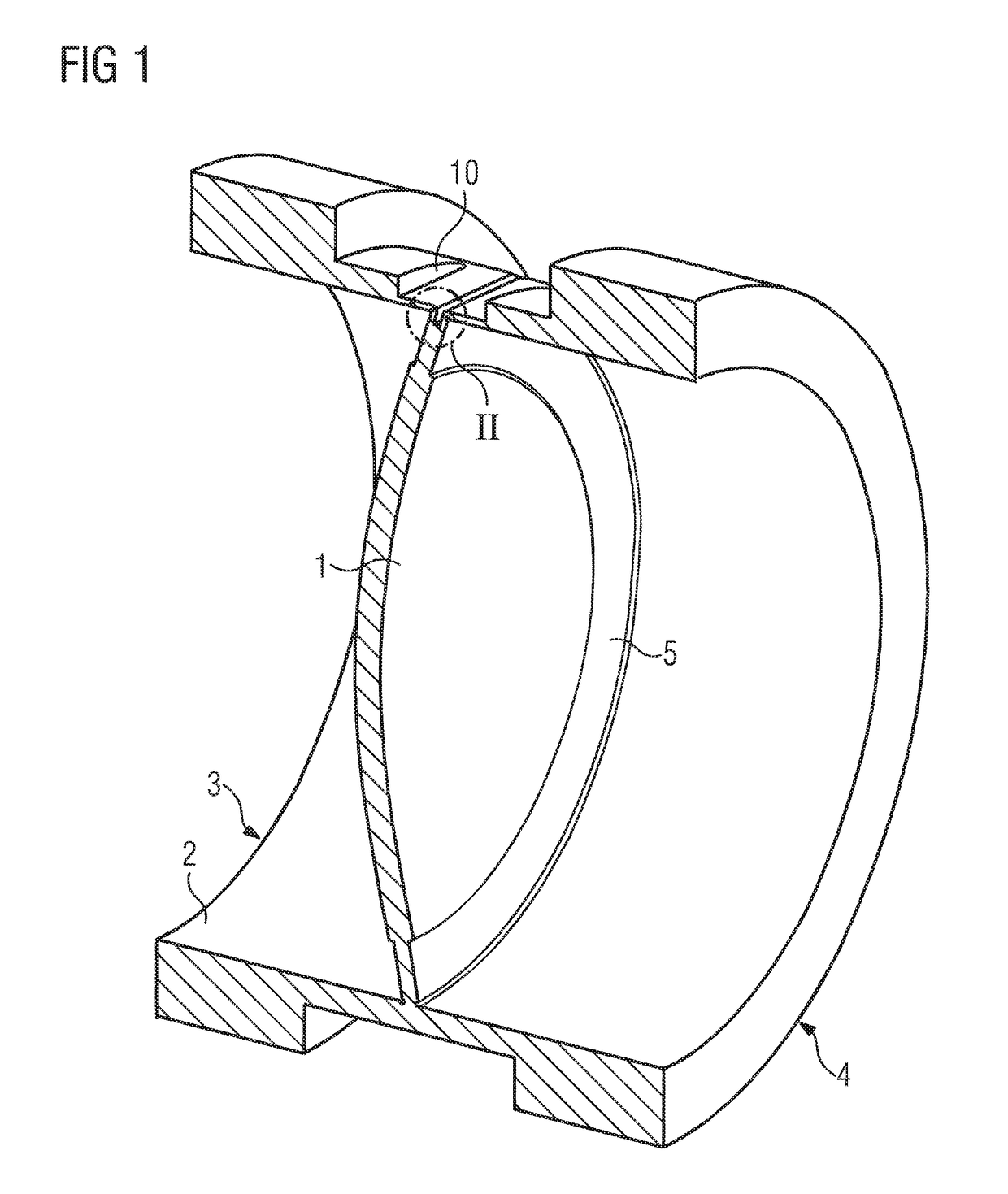
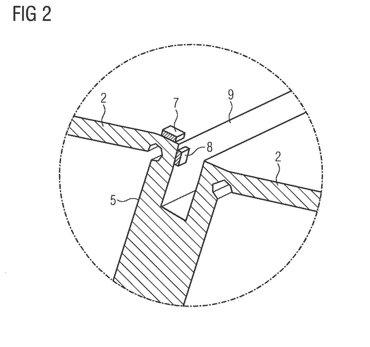
[0019]The basic arrangement of a diaphragm 1 in the cross section of a tube 2 is clearly visible in the longitudinal section shown in FIG. 1. When the illustrated pressure sensor arrangement is used in a pressure measuring transducer for process instrumentation, the two ends 3 and 4 of tube 2 can each be sealed by a cap (not shown in FIG. 1) via which a process medium having the pressure to be measured can be supplied to one side of the diaphragm 1, in the case of an absolute pressure sensor, or to both sides of the diaphragm 1, in the case of a differential pressure sensor. An electronics unit for evaluating the electrical signals produced by the pressure sensor arrangement that are dependent on the pressure to be measured can be of conventional design and is likewise not shown in FIG. 1. It is clear from FIG. 1 that the mechanical configuration of a differential pressure measuring cell using a dia...


PUM


Abstract

A pressure sensor arrangement includes a tube with a diaphragm to pressure to be measured is applied arranged in the cross-section of the tube, wherein the diaphragm is fastened to the tube inner wall via an articulation extending along the circumferential region of the diaphragm, where deformation of the diaphragm results in rotation of the articulation directly on the wall of the tube which can therefore be detected from the outside by suitable structure such that that strain sensors, for example, which can be used to detect deformation are advantageously not in contact with the process medium and there is advantageously no need for a pressure-tight bushing for electrical signals, and where the pressure sensor arrangement has a particularly simple structure and can be advantageously used in measuring transducers for process instrumentation.

Description

CROSS-REFERENCE TO RELATED APPLICATIONS[0001]This is a U.S. national stage of application No. PCT / EP2016 / 057979 filed Apr. 12, 2016. Priority is claimed on German Application No. DE102015216626.0 filed Aug. 31, 2015, the content of which is incorporated herein by reference in its entirety.BACKGROUND OF THE INVENTION1. Field of the Invention[0002]The invention relates to a pressure sensor arrangement comprising a tube having a diaphragm to which pressure to be measured is applied disposed in a cross-section of the tube, and to a measuring transducer for process instrumentation having the pressure sensor arrangement.2. Description of the Related Art[0003]In industrial process plants, a variety of field devices for process instrumentation are used to control processes. Measuring transducers are used to detect process variables such as temperature, pressure, flow rate, fill level, density or gas concentration of a medium. The process flow can be influenced by final control elements as a...

Claims


Application Information

Patent Timeline
IPC IPC(8): G01L9/00G01L13/02G01L23/18
CPCG01L9/0064G01L13/025G01L23/18G01L9/0052
Inventor ERDLER, GILBERT ALEXANDERVON DOSKY, STEFAN
Owner SIEMENS AG
Learn More