Self-heat-dissipation pressure-reducing valve

Active Publication Date: 2018-08-23
CHINA UNIV OF MINING & TECH
View PDF0 Cites 3 Cited by
  • Summary
  • Abstract
  • Description
  • Claims
  • Application Information

AI Technical Summary

Benefits of technology

The patent is about a valve that can effectively cool its part using a heat-sinking system. The valve core is made of a carbon steel heat pipe connected to heat-dissipation fins. The valve is solidly soldered with tin and coated with a wear-resistant material to increase its ability to resist erosion. The device also includes a fan shell with conical roller bearings that are fastened to the valve body and the inlet flange, allowing the fan blades to rotate and produce wind energy to cool the valve. This helps to prolong the service life of the valve and reduce maintenance costs. Additionally, the device reduces cavitation damage to the valve and its seat pocket, achieving pressure reduction and improving its overall performance.

Problems solved by technology

Therefore, during operation, the pressure-reducing valve needs to bear not only a considerably high pressure, but also a thermal shock and a thermal load caused by a drastic temperature change in a short time.
In use, the pressure-reducing valve may undergo creep, oxidation due to overheating, carburizing, corrosion, and so on, which shortens the service life of the valve.
In addition, when the temperature of a fluid in the pressure-reducing valve is excessively high, the valve is unable to effectively dissipate the heat in a short time.
Therefore, a throttle part of the valve may lose the pressure adjusting function due to cavitation, abrasion and so on.
As a result, the operation of the device is affected, and the production and operation of the whole equipment are shut down, which reduce the production efficiency and cause huge economic losses.
The prior art basically deals with heat dissipation of a valve by using heat-dissipation fins, or by means of water cooling or air cooling depending on external power, but fails to satisfactorily dissipate heat from a high-temperature and high-pressure medium.
Moreover, the existing solutions all rely on external power to reduce the valve temperature, and cannot utilize the structure of valve itself to implement heat dissipation.

Method used


Image

  • Self-heat-dissipation pressure-reducing valve
  • Self-heat-dissipation pressure-reducing valve
  • Self-heat-dissipation pressure-reducing valve

Examples


Embodiment Construction

[0038]The embodiment of the present invention is further described in detail below with reference to the accompanying drawings:

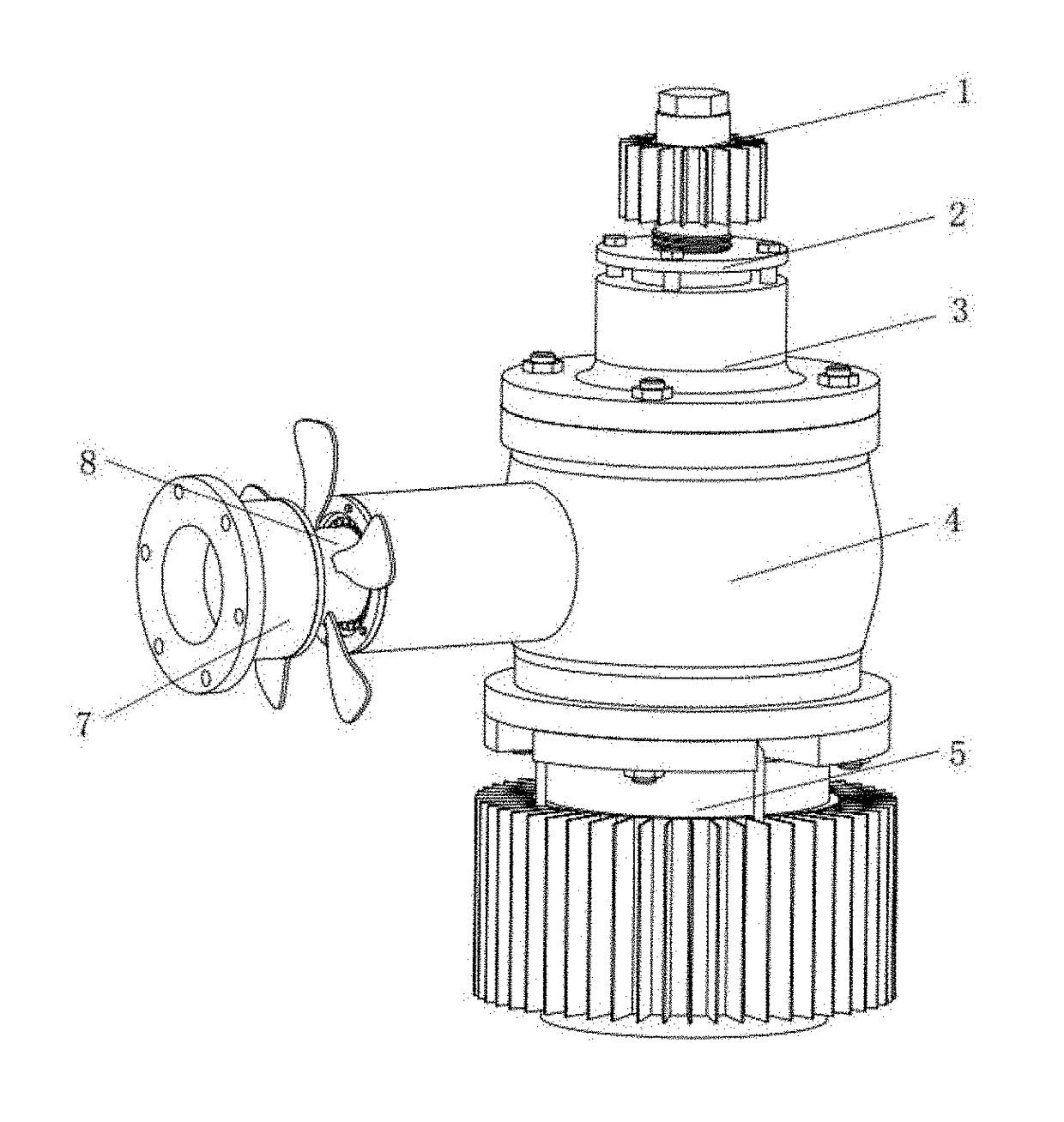
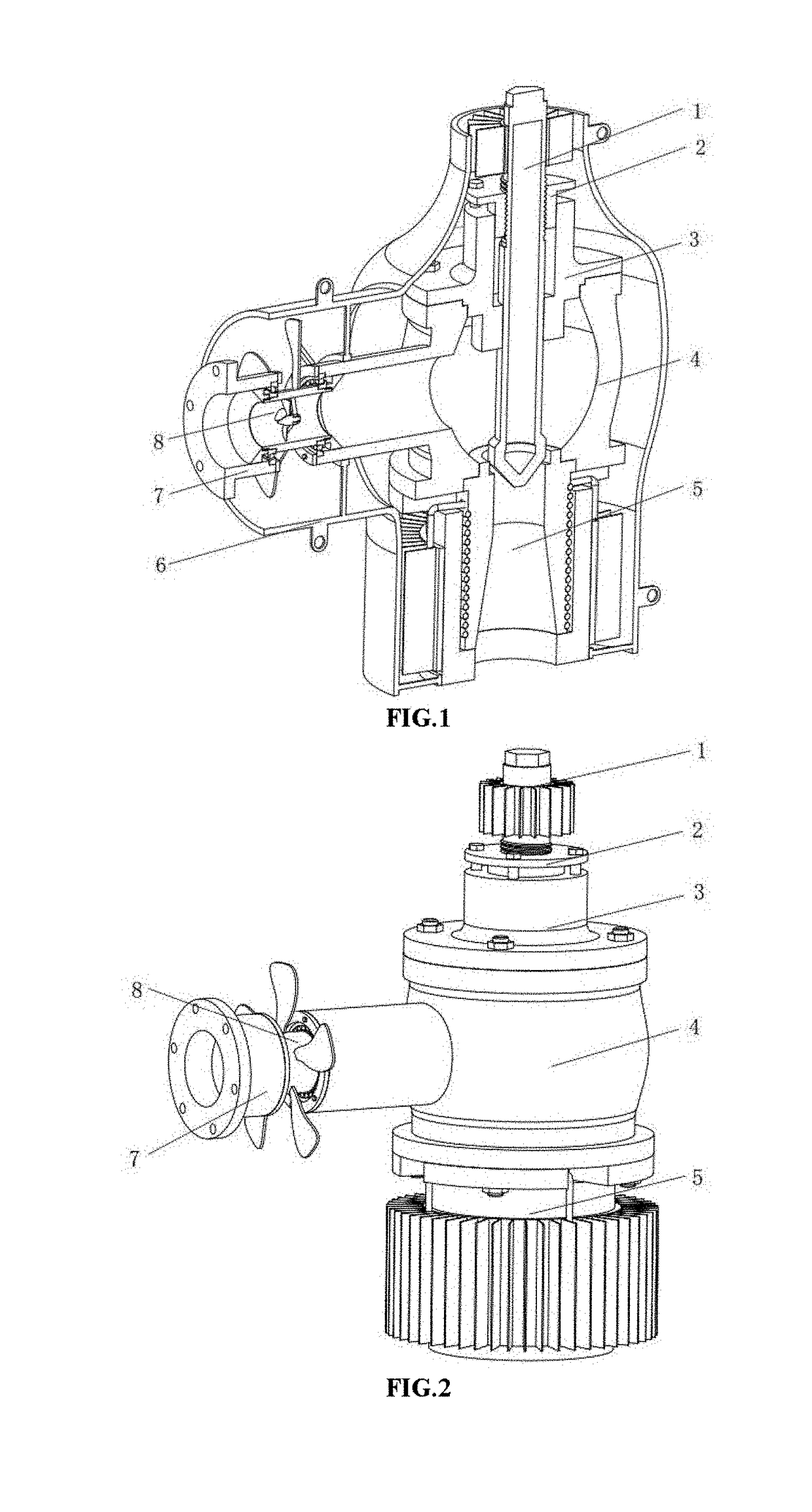
[0039]As shown in FIG. 1 and FIG. 2, a self-heat-dissipation pressure-reducing valve of the present invention includes an air guide hood 6 and a self-heat-dissipation reducing valve main body. The self-heat-dissipation pressure-reducing valve main body includes a heat-dissipation valve core 1, an upper valve deck 2, a guiding valve deck 3, a valve body 4, a heat-dissipation valve seat 5, an inlet flange 7, and a turbine-type heat dissipation device 8.

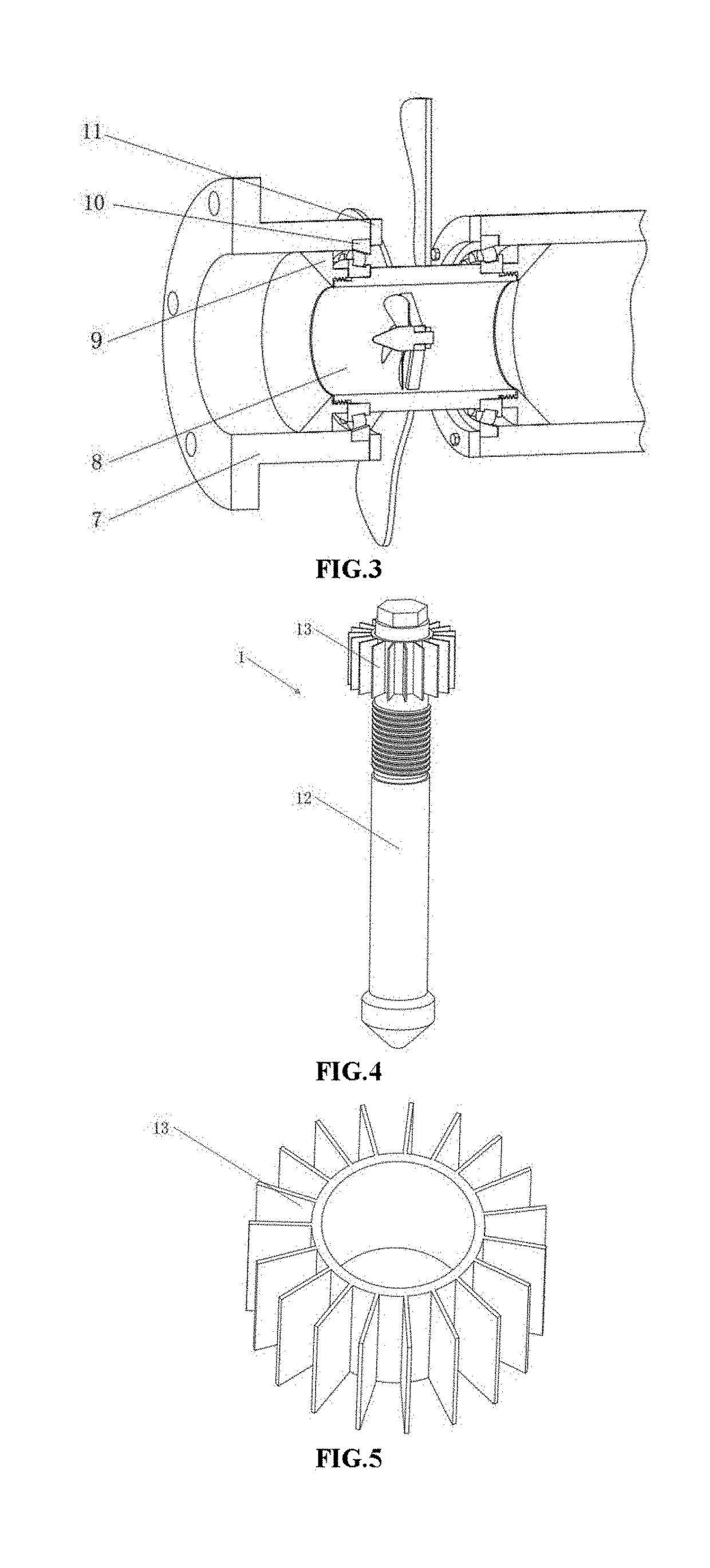
[0040]As shown in FIG. 5, the heat-dissipation valve core 1 includes a valve core 12 and valve core heat-dissipation fins 13. A head portion of the valve core 12 is of a projecting tapered shape, external threads are provided on a middle section near the tail of the valve core 12, and the valve core heat-dissipation fins 13 are fitted on the tail of the valve core 12 and fixed by means of tin soldering. The valv...


PUM


Abstract

A self-heat-dissipation pressure-reducing valve includes: a heat-dissipation valve core, an upper valve deck, a guiding valve deck, a valve body, a heat-dissipation valve seat, an air guide hood, and a turbine-type heat dissipation device. The heat-dissipation valve core is formed by a valve core composed of a heat pipe, and valve core heat-dissipation fins. The heat-dissipation valve seat includes a valve seat pocket, a valve seat shell, heat pipes, and valve seat heat-dissipation fins. An outer circumferential surface of the valve seat pocket is wound with multiple heat pipes fixed to the valve seat heat-dissipation fins. The turbine-type heat dissipation device includes a fan shell provided at a medium inlet, and a turbine. The turbine is lashed by a medium to turn the fan shell, and wind is guided in one direction through the external air guide hood to implement heat dissipation.

Description

BACKGROUND OF THE INVENTION1. Field of the Invention[0001]The present invention relates to a pressure-reducing valve, and in particular, to a self-heat-dissipation pressure-reducing valve applicable to petrochemical and coal-chemical equipment used in industrial and mining enterprises.2. Description of Related Art[0002]A high-pressure differential reducing valve is key equipment in petrochemical industry, coal-chemical industry, and so on. Because of particularities of industries such as coal-chemical industry, the pressure-reducing valve generally works in a large-caliber pipeline for conveying a high-temperature and high-pressure medium. Especially, in a coal liquefaction process, the high-pressure differential reducing valve relieves the pressure of a medium above 400° C. from 19 MPa to 2.8 MPa, where a peak flow speed of the medium reaches up to hectometers per second. Such a pressure-reducing valve is a valve used in the most demanding condition in the direct coal liquefaction ...

Claims


Application Information

Patent Timeline
IPC IPC(8): F16K49/00F16K1/02F16K1/38F16K1/42F16K27/02F16K27/12
CPCF16K49/00F16K1/02F16K1/38F16K1/42F16K27/0254F16K27/12F16K49/005Y10T137/6525
Inventor LIU, XIUMEILI, BEIBEIXU, HUAWENHE, JIEWANG, BINGYANGJIAO, MINGLISUN, FUHUAWANG, HAIBINGLIU, XIAOCHENDAI, ZHENZHENXIE, ZIHAO
Owner CHINA UNIV OF MINING & TECH
Why Eureka
Try Eureka