
Long-Range Viewing Apparatus

a viewing apparatus and long-range technology, applied in the field of long-range viewing apparatuses, can solve the problems of multiple imaging apertures, large product sizes, increased glare created by reflected light, etc., and achieve the effect of less complexity and more robustness

Inactive Publication Date: 2018-08-09
SESANTI LTD
View PDF4 Cites 0 Cited by
  • Summary
  • Abstract
  • Description
  • Claims
  • Application Information

AI Technical Summary

Benefits of technology

The invention is a camera system with two cameras placed side by side, which reduces glare and noise from reflected light. Compared to other digital foveal zoom cameras, it has no moving parts, making it more robust and suitable for demanding applications. The system also uses foveal vision to provide a high-resolution central region and information about the surrounding environment, making it easier to find the desired entity without extensive scanning. The processing of the combined image data from the two cameras is less computationally intensive than using only high-quality image data from the second camera. Overall, the invention provides a more efficient and reliable camera system for various applications.

Problems solved by technology

Where multiple cameras are used in a side-by-side configuration in current forms of foveal vision technology, this requires multiple imaging apertures and larger product size.
Multiple imaging apertures can also carry with it a further disadvantage in the increased amount of glare created by reflected light.
One of the most critical disadvantages to the use of multiple imaging apertures is, however, the high incidence of parallax errors.

Method used


Image

  • Long-Range Viewing Apparatus
  • Long-Range Viewing Apparatus
  • Long-Range Viewing Apparatus

Examples


Embodiment Construction

[0022]Specific embodiments will now be described by way of example only, and with reference to the accompanying drawings, in which:

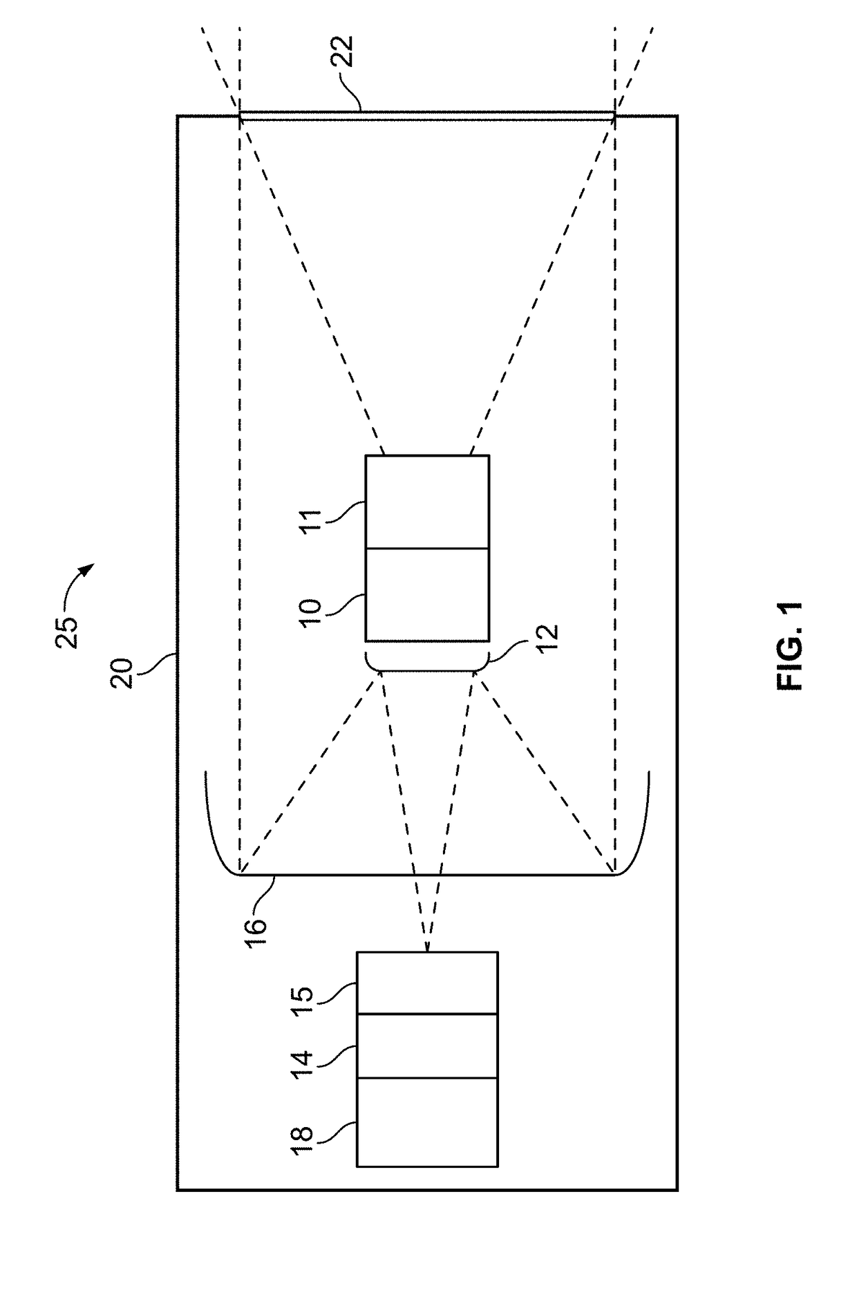
[0023]FIG. 1 shows a schematic view of a preferred embodiment of a long-range viewing apparatus according to a first aspect of the present invention;

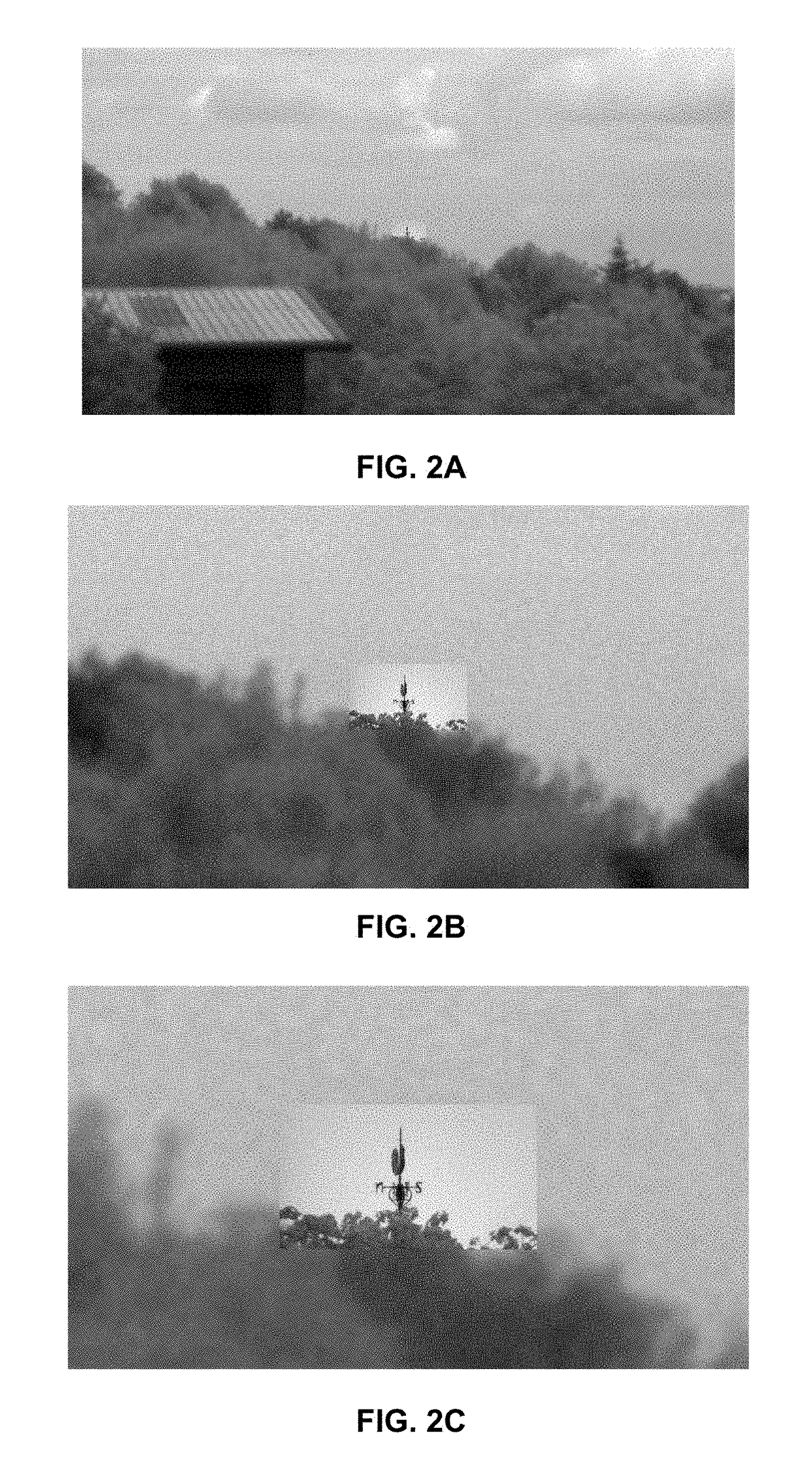
[0024]FIG. 2a-c show iteratively zoomed example images output from a long-range viewing apparatus of FIG. 1; and

[0025]FIG. 3 shows the long-range viewing apparatus of FIG. 1 further comprising a display means.

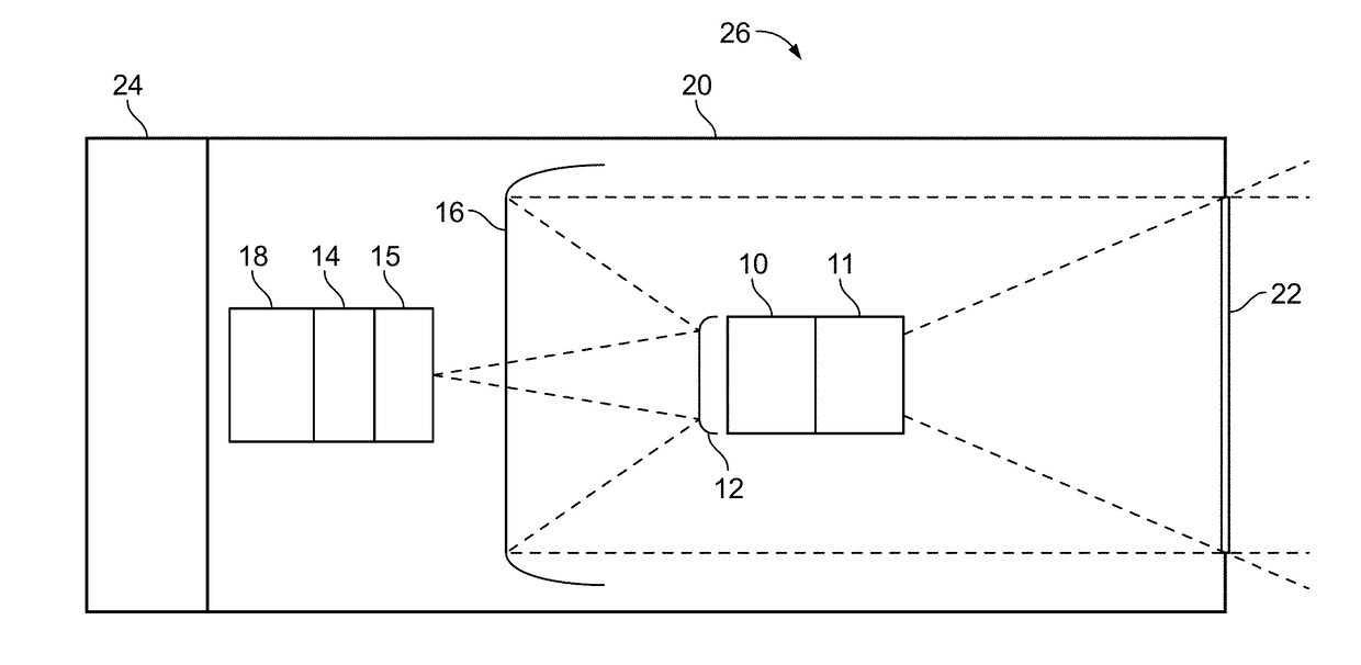
[0026]Referring to FIG. 1, a schematic view is provided in which there is illustrated a long-range viewing apparatus 25 in accordance with a first embodiment of the invention, enabling all-in-one coaxial digital foveal imaging and zoom functionality.

[0027]The apparatus 25 comprises a substantially rectangular housing 20, with a single imaging aperture 22 in a side face. The aperture 22 provides for transit of light accessible to a first camera sensor 10 through a therein combined first camera lens assem...


PUM


Abstract

A long-range viewing apparatus is described, the long-range viewing apparatus arranged to provide an all-in-one solution to combining two videos streams obtained coaxially through a single imaging aperture. A long-range viewing apparatus comprising, a housing; a first camera within the housing; a second camera within the housing; and a processing element; wherein the processing element is arranged to combine images from the first and second cameras; wherein the processing element is further arranged to scale images from the first and second cameras; wherein the processing element is further arranged to crop images from the first and second cameras; characterised in that, the first camera is positioned coaxially in front of the second camera; and the housing comprises a single imaging aperture. The invention aims to achieve real-time digital foveal zoom capabilities in a physically robust, low-weight, low-complexity and small form factor assembly suitable for demanding applications.

Description

FIELD OF THE INVENTION[0001]The present invention relates to a long-range viewing apparatus, in particular a long-range viewing apparatus providing coaxial digital foveal zoom capabilities.BACKGROUND TO THE INVENTION[0002]Conventional zoom lens systems utilize a lens assembly providing a variable focal length and therefore give the user the benefit of being able to dynamically adjust the field of view of a camera system. This optical zoom technology typically uses a plurality of lenses within a housing, wherein the positioning of the lenses within the housing may be adjusted to provide for the varying of the focal length. Focussing upon a desired point is therefore provided for in conventional zoom technology.[0003]There are, however, a number of drawbacks to the more traditional zooming systems. A primary drawback to this technology is the level of complexity inherent in having a system comprising a number of moving parts. Complex optical zoom systems can comprise upwards of thirty...

Claims


Application Information

Patent Timeline
Patent Type & Authority Applications(United States)
IPC IPC(8): G03B19/02G02B17/08G02B7/34
CPCG03B19/023G02B17/08G02B7/34G02B17/061G02B23/12G06T5/50H04N5/272G06T2207/10148G06T2207/20221H04N23/50H04N23/951H04N5/265G03B17/17H04N23/45H04N23/00
Inventor BATES, ANDREW JAMES
Owner SESANTI LTD
Learn More