Method for Liquid Air Energy Storage with Fueled and Zero Carbon Emitting Power Output Augmentation
a technology of energy storage and liquid air, applied in the direction of fuel air intake, lighting and heating apparatus, fuel treatment, etc., can solve the problems of increasing the charging power and the required volume of the liquid air tank at the laes facility, and producing liquid air during off-peak hours is an energy-intensive process
- Summary
- Abstract
- Description
- Claims
- Application Information
AI Technical Summary
Benefits of technology
Problems solved by technology
Method used
Image
Examples
first embodiment
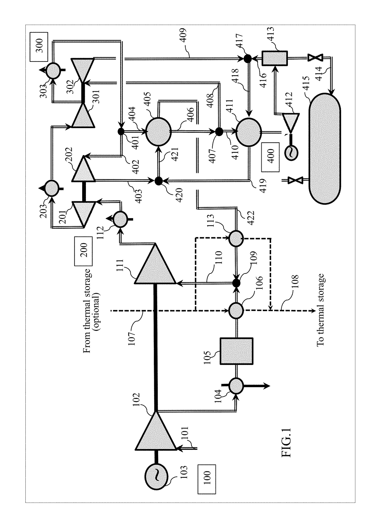
[0027]The practical realization of the invented method for energy storage with fueled and zero carbon emitting power output augmentation may be performed through the integration between the medium-to-large scale Liquid Air Energy Storage (LAES) facility and fueled supercharged reciprocating Internal Combustion Engine(s) (ICE) described below. Such the integration makes possible to achieve the main invention goals: to maximize power output and round-trip efficiency of the energy storage and to minimize carbon dioxide emissions from the fueled equipment (ICE and duct burner). The LAES operation includes the modes of its charging and discharging. FIG. 1 shows schematically the first embodiment for implementing the charging the energy storage with a liquid air valid both for large (above 40 MW) and medium (below 40 MW) scale LAES facilities. Here the involved equipment packages are designated as:
[0028]100—compressor train with associated equipment;
[0029]200—warm turbo-expander—booster c...
second embodiment
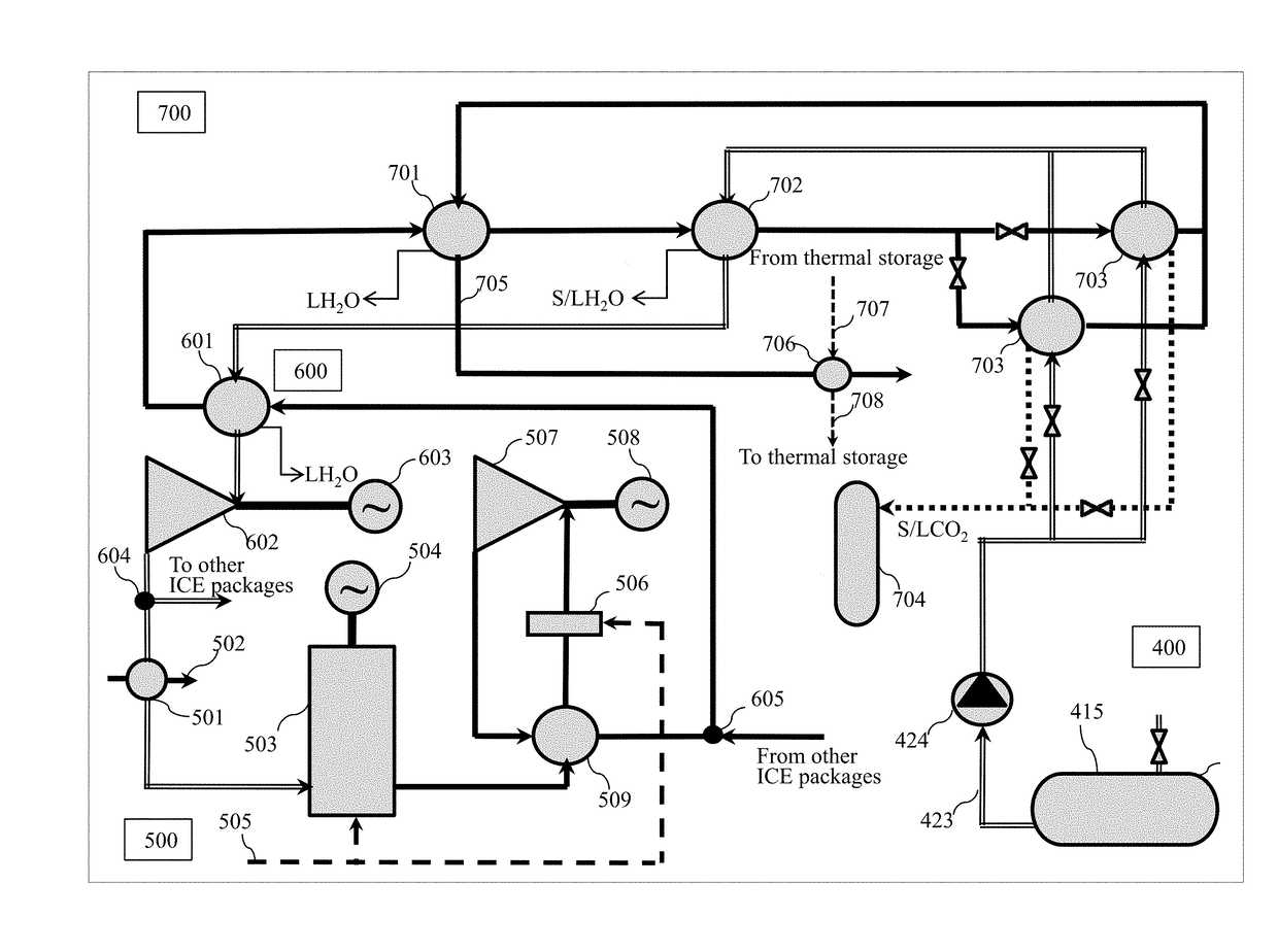
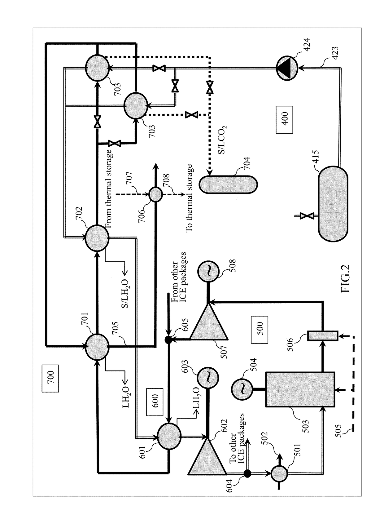
[0038]FIG. 2 shows schematically the second embodiment for implementing the discharge of the large-scale (above 40 MW) energy storage with increase in temperature of the ICE exhaust gases in the downstream installed duct burner up to value not exceeding 750° C. and with cryogenic capturing the CO2 emissions. Here the involved equipment packages are designated as:
[0039]400—liquid air storage equipment;
[0040]500—supercharged reciprocating ICE package;
[0041]600—HP air expander train; and
[0042]700—dewatering and CO2 cryogenic capture equipment package.
[0043]Operation of the large-scale energy storage in discharge mode is performed as follows. A stream of liquid air 423 is extracted from the storage vessels 415 at a bottom discharge pressure exceeding 2 barA and pumped by a pump 424 up to top discharge pressure selected in the range between 40 and 200 bar. The pumped liquid air stream is delivered into a package 700 which is destined for re-gasifying of this air in the heat exchanger 703...
third embodiment
[0049]FIG. 3 is a schematic view of the third embodiment for implementing the discharging the large-scale (above 40 MW) energy storage with an increase in temperature of the ICE exhaust gases in duct burner up to a value not exceeding 1000° C. and with cryogenic capturing the CO2 emissions from the exhaust gases stream. As compared to the scheme presented in the FIG. 2, a temperature of exhaust gases at the inlet of the low-pressure turbo-expander 507 is increased by 150-250° C., resulting in enhancement of total power output of energy storage by about 3-5%. At the same time, a mentioned restriction on the re-gasified air temperature at the inlet of the high-pressure turbo-expander 602, which should be below or equal to 600° C., remains valid. The method, making possible to solve this dilemma, is described below without repeated description of the packages 400, 600 and 700, which are identical in design and operation to those described above as applied to the FIG. 2.
[0050]Similar to...
PUM
 Abstract
Description
Claims
Application Information
 - R&D
- Intellectual Property
- Life Sciences
- Materials
- Tech Scout
- Unparalleled Data Quality
- Higher Quality Content
- 60% Fewer Hallucinations
Browse by: Latest US Patents, China's latest patents, Technical Efficacy Thesaurus, Application Domain, Technology Topic, Popular Technical Reports.
© 2025 PatSnap. All rights reserved.Legal|Privacy policy|Modern Slavery Act Transparency Statement|Sitemap|About US| Contact US: help@patsnap.com


