
X-ray apparatus, data processing apparatus and data processing method

a technology of x-ray apparatus and data processing apparatus, applied in the field of x, can solve the problems of narrowing the conditions for detecting foreign objects, limiting the imaging object or imaging conditions, and applying techniques, so as to reduce the number of detected x-ray photons, improve accuracy, and reduce the effect of changes

Active Publication Date: 2018-08-02
JOB
View PDF5 Cites 18 Cited by
  • Summary
  • Abstract
  • Description
  • Claims
  • Application Information

AI Technical Summary

Benefits of technology

The patent describes a method for detecting X-rays transmitted through an object using a detector with a continuous X-ray spectrum. The method uses beam-shaped X-rays and detects the amount of X-rays transmitted through the object by measuring the number of X-ray photons in different energy bins. The method corrects the detected counts using a linear target characteristic to account for changes in X-ray energy caused by physical phenomena such as beam hardening. This results in more accurate and reliable detection signals. Additionally, the use of continuous-spectrum X-rays improves the signal-to-noise ratio.

Problems solved by technology

Thus, detection conducted under such specific conditions limits imaging objects or imaging conditions to which the technique is applied, that is, narrows the conditions for detecting foreign matters.
Specifically, the dual energy technique described in these publications offers accuracy that is so low as not to reflect the difference in attenuation degree of the X-ray photon energy and materials, and gives little consideration to the electric noise or nonlinear characteristics of X-ray detection circuits, which may be unignorable problems.
Accordingly, it is mostly difficult to detect the types or natures of foreign matters.
This means that it is difficult to identify the types or natures of the materials the X-rays penetrate.

Method used


Image

  • X-ray apparatus, data processing apparatus and data processing method
  • X-ray apparatus, data processing apparatus and data processing method
  • X-ray apparatus, data processing apparatus and data processing method

Examples


first embodiment

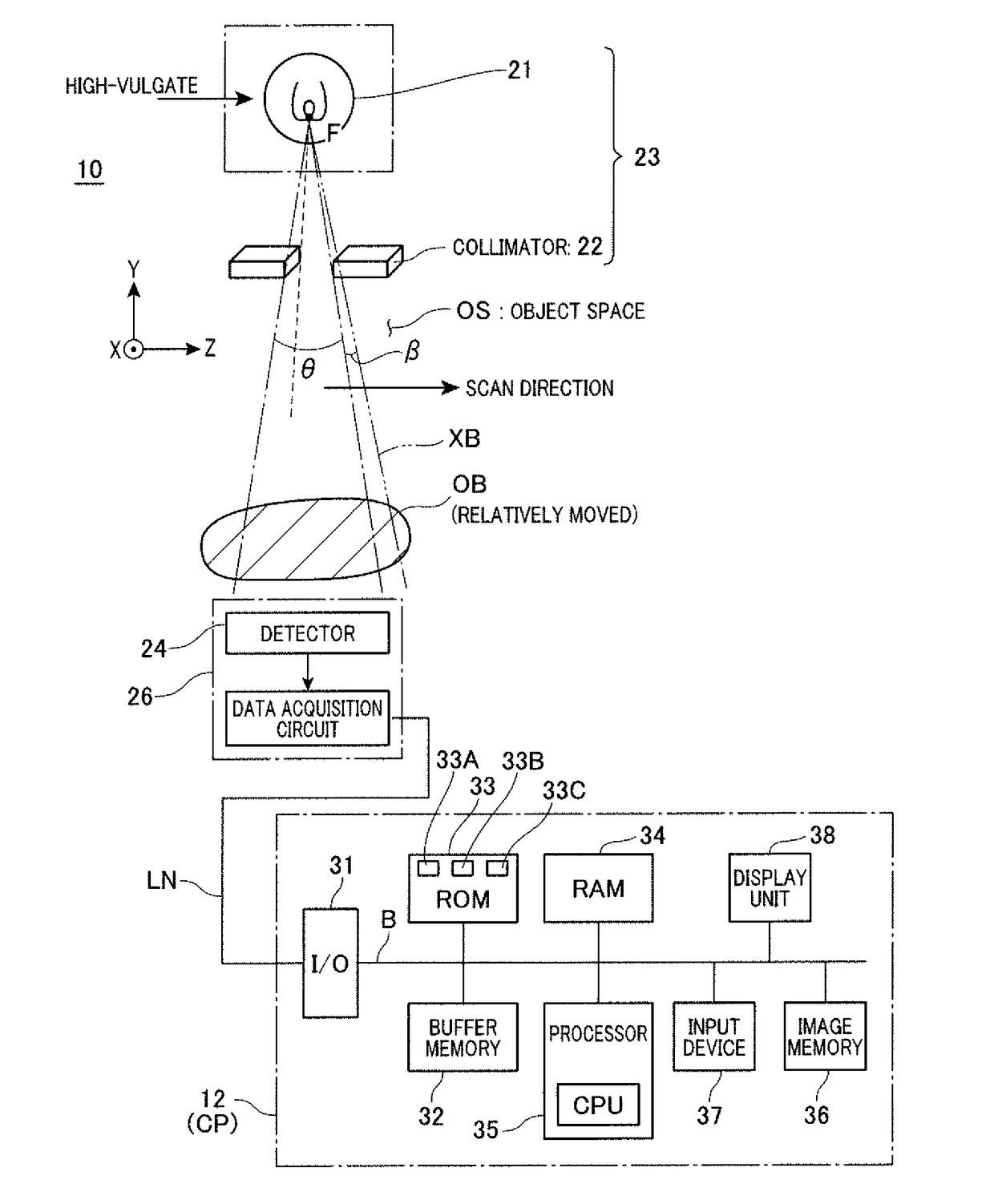
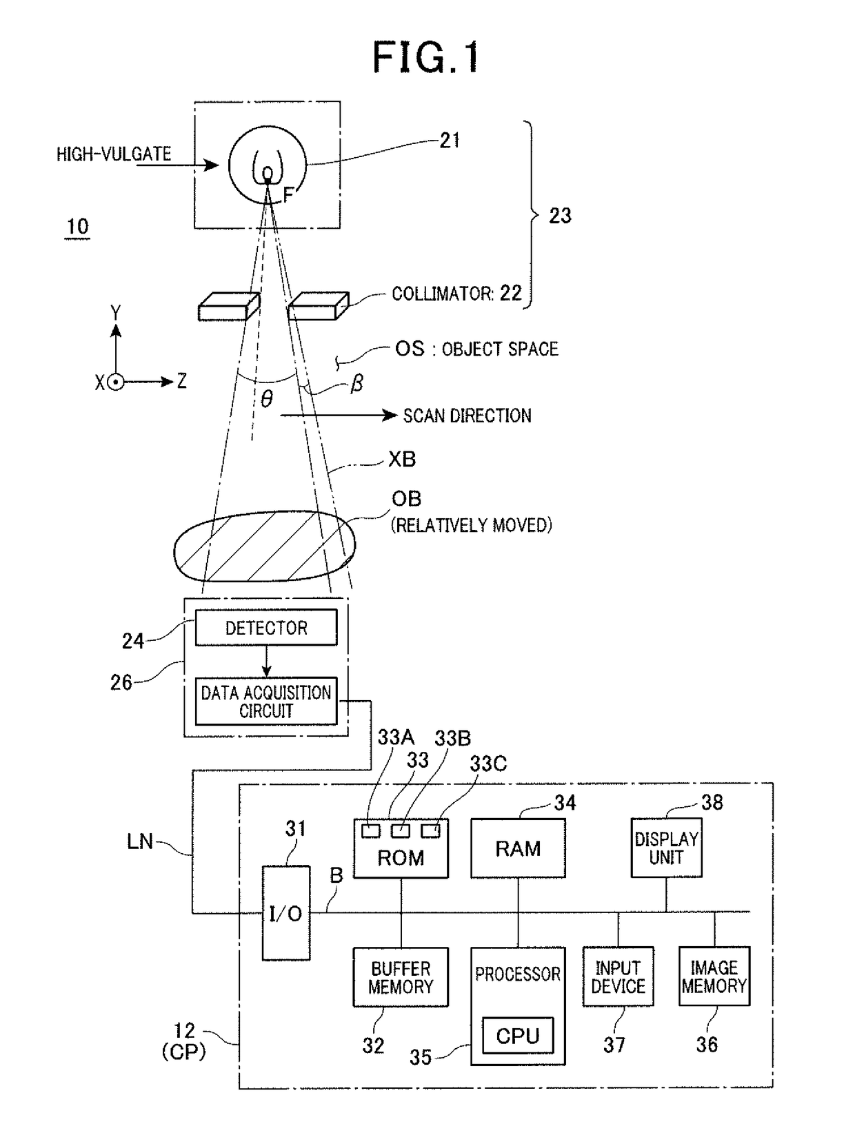
[0052]Referring to FIG. 1 to FIG. 12, a first embodiment of the X-ray apparatus (and the data processing apparatus) will now be described.

[0053]FIG. 1 outlines the X-ray apparatus provided according to the first embodiment. This X-ray apparatus can be provided as apparatuses for X-ray foreign-matter inspection or X-ray mammography. These apparatuses are directed to acquiring tomographic images and / or projected images of an object being inspected. In particular, the apparatuses can also be directed to inspecting whether or not foreign matter is attached to or misplaced inside an object (for example, a food item) and / or identifying (estimating, determining) the type and / or property of the foreign matter. The foreign matter is a substance other than materials composing a non-contained normal object. Such substances are metal pieces such as aluminum pieces or insects such as cockroaches. An apparatus to check existence of foreign matter is known as an X-ray foreign-matter inspecting app...

first modification

[0148]First of all, the linear target characteristic explained with FIG. 7 can be modified in various modes. The foregoing target characteristic is just one example. How to generate the target characteristic, which has been stated, is also just one example and can be designed in another way.

[0149]For instance, a linear line can be set as a target characteristic which connects, as shown in FIG. 7, the origin of the coordinate system and an intersection point where a representative thickness tr of an object and an X-ray attenuation amount μtr corresponding to the representative thickness tr. Such a representative thickness tr can be set by referring to a plurality of mutually different thicknesses t of a substance which is similar in type or which can be approximated in X-ray transmission properties to an object being examined. This target characteristic can be calculated by the processor 35 or an external processing device in advance, and data of the target characteristic can be stor...

second modification

[0150]A second medication also relates to another way of setting the target characteristic.

[0151]This setting technique is to set a linear line serving as a target characteristic, which has a designated gradient and which passes the origin of the coordinate system. The gradient is set to be a linear attenuation coefficient calculated based on a theoretical value for an effective or fixed energy in each of the X-ray energy bins.

[0152]A case which uses an effective energy in each of the X-ray energy io bins will now be described. FIG. 13 pictorially exemplifies an X-ray energy spectrum. In this spectrum, similarly to that shown in FIG. 3, the three energy bins, Bin1 to Bin3, are set, in which an effective energy amount Ei in the respective energy bins, Bin1 to Bin3, can be calculated based on the following formula:

∫ETHiEIC(E)dE=½∫ETHi+1Ei+1C(E)dE

, where i=1, 2 and 3.

[0153]This calculation shows that a count of X-ray photons counted between an energy threshold ETHi to an effective ene...


PUM

PropertyMeasurementUnit
pixel sizeaaaaaaaaaa
sizeaaaaaaaaaa
sizeaaaaaaaaaa

Abstract

Based on counts detected by a photon counting detector, a characteristic of X-ray attenuation amounts μt is acquired for each X-ray energy bin. This characteristic is defined by a plurality of mutually different known thicknesses t and linear attenuation coefficients in the X-ray transmission direction. This substance is composed of a material which is included in an object and which is the same in type as the object or which can be regarded as being similar to the object in terms of the effective atomic number. Correcting data for replacing the characteristic of the X-ray attenuation amounts μt by a linear target characteristic are calculated. The linear target characteristic is set to pass through the origin of a two-dimensional coordinate having a lateral axis assigned to thicknesses t and a longitudinal axis assigned to the X-ray attenuation amounts μt. The correcting data are calculated for each X-ray energy bin.

Description

TECHNICAL FIELD[0001]The present invention relates to an X-ray apparatus that scans an object with X-rays to acquire X-ray transmission data and checks states of the object based on the acquired data, and a data processing unit which can be installed in the X-ray apparatus, and in particular, the X-ray apparatus which uses X-rays with a continuous energy spectrum and the data processing apparatus which can be installed in this X-ray apparatus.BACKGROUND ART[0002]In recent years, inspection using X-ray beams to check the internal state of an object has been widely used in various fields, such as foreign matter inspection of food, baggage inspection, and medical X-ray mammography.[0003]For example, airports, public facilities, or the like use a content inspection that is an inspection of the types and shapes of baggage or mail contents, which is carried out without opening the baggage or mail. It is desired that such a content inspection should find out the presence of foreign matters...

Claims


Application Information

Patent Timeline
Patent Type & Authority Applications(United States)
IPC IPC(8): A61B6/00G01N23/04G01N23/083
CPCA61B6/584G01N23/04G01N23/083A61B6/00G01N23/18G01N33/025G01N33/10G01N23/087G01N2223/6126G01N2223/618
Inventor YAMAKAWA, TSUTOMUYAMAMOTO, SHUICHIROOKADA, MASAHIRO
Owner JOB
Learn More