
Free-breathing and self-navigated MRI method for deformable motion derivation

Active Publication Date: 2018-07-19
WASHINGTON UNIV IN SAINT LOUIS
View PDF7 Cites 8 Cited by
  • Summary
  • Abstract
  • Description
  • Claims
  • Application Information

AI Technical Summary

Benefits of technology

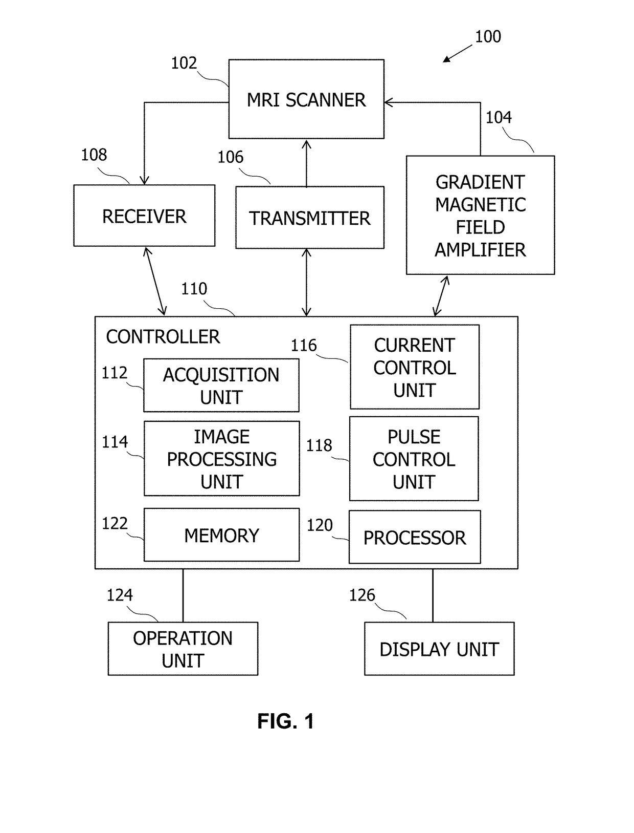
This patent describes a system and method for producing motion-corrected MR images of a patient. The system includes an MRI scanner and a controller that detects motion and processes the MR imaging datasets to identify a motion cycle with multiple phases. The data is then partitioned into groups to generate the MR images. The technical effects of this invention include reduced image blurring caused by respiratory motion, improved image quality, and improved accuracy in detecting abnormalities in the patient's brain and spine.

Problems solved by technology

Respiratory and cardiac motion over the course of MR data acquisition sequences causes artifacts and blurring in four dimensional (4D) MR images, thereby reducing the effectiveness of MR imaging.
Further, the motion effects on MR imaging may reduce the potential benefits of advanced medical imaging methods that combine MR with other imaging modalities, such as simultaneous PET / MR imaging.
However, breath-holding acquisition schemes limit the acquisition time to only tens of seconds per breath hold.
Moreover, the breath-holding method is challenging for some patients who have difficulty in holding their breath.
Moreover, the bellows signal may also be contaminated by respiratory drift.
However, existing navigator schemes have at least several drawbacks, including complex sequence implementation, lengthened MR data acquisition time, and magnetization disturbances during the MR imaging scan.
Motion correction of PET imaging data may rely on the modeling of changes in the target anatomy through the scanning period using PET data, and may be complex to implement due to the deformable nature of organs within the target anatomy.

Method used


Image

  • Free-breathing and self-navigated MRI method for deformable motion derivation
  • Free-breathing and self-navigated MRI method for deformable motion derivation
  • Free-breathing and self-navigated MRI method for deformable motion derivation

Examples


example 1

g of Respiratory Image Phantom

[0184]To assess the effect of data acquisition and motion resolution methods under controlled conditions, the following experiments were conducted.

[0185]A respiratory motion phantom referred to herein as “Chest-R” was constructed as shown in the photograph of FIG. 11A. Chest-R included a bellow that was inflated and deflated by an adjustable ventilator pump (Model 607, Harvard Apparatus) with adjustable frequency and amplitude outputs. As shown in FIG. 11A, the bellow, which consisted of a 0.5 L neoprene ventilation bag was immersed in a sodium polyacrylate (˜10 g / L) gel. The bellow's inflation and deflation cycle was modulated by varying the impedance between the ventilator pump and the bellow using variable diameter and length tygon tubing. Neoprene pockets were attached to the bellows to permit the insertion of PET phantoms for PET / MR simulations. Chest-R was configured to generate deformable motion that resembled respiratory motion.

[0186]The Chest-R...

example 2

Motion Correction on In Vivo MR Signal Spectra

[0188]To assess the effect of motion correction on in vivo MR signal spectra, the following experiments were conducted.

[0189]The Chest-R phantom was subjected to MR imaging in a manner similar to the methods described in Example 1 to derive a respiratory motion cycle using the self-navigated respiratory correction methods described above in various aspects. The Chest-R phantom was imaged during six different simulated respiratory cycles characterized by three different motion frequencies of 10, 20, and 30 rpm and two air volumes of 400 and 600 cc, making for six different settings, were tested. The MRI acquisition parameters were as follows: TE / TR=1.99 ms / 3.84 ms, matrix size=320×320, field of view (FOV)=240 mm×240 mm, slab thickness=163.2 mm, number of partitions=48, partial Fourier factor=6 / 8, reconstructed slices per slab=96 (yielding a slice thickness of 1.7 mm). The resulting voxel size for the phantom study was 0.75×0.75×1.7 mm3. S...

example 3

Phase Tuning on Respiratory Motion Detection

[0192]To assess the effect of phase tuning on respiratory motion detection, the following experiments were conducted.

[0193]One healthy subject was subjected to two MR imaging scans using two different single-slice gradient recalled echo (GRE) sequences. The first GRE protocol was as follows: TE / TR=3.1 ms / 5.6 ms, slice thickness=3 mm, matrix size=192×126, in-plane resolution=1.56×1.56 mm, number of sequence repetitions=500, and total scan time=67 seconds. The acquisitions were sagittal with the readout axis lying along the SI axis of the subject. Generalized autocalibrating partially parallel acquisitions (GRAPPA) was used for accelerating the acquisition so that each image could be acquired in 134.4 ms. In this time period, it was possible to observe the motion of the liver during respiration. The second GRE protocol was similar to the first protocol except that the slice thickness was set to 250 mm, rather than 3 mm.

[0194]The thick-slice ...


PUM


Abstract

Systems and methods for producing motion-corrected MR images that include an MRI scanner with a plurality of coils in which the plurality of coils is configured to detect a plurality of MR imaging datasets are provided. Each MR imaging dataset includes a plurality of MR signals detected by one coil of the plurality of coils. The system further includes a controller operatively coupled to the MRI scanner that includes at least one processor and a non-volatile memory. The controller further includes an image processing unit configured to receive the plurality of MR imaging datasets associated with the plurality of coils, identify a motion cycle using an automated motion detection method, and to partition the plurality of MR imaging datasets into a plurality of image groups, in which each image group comprises a portion of the plurality of MR imaging datasets associated with one of the phases of the motion cycle.

Description

CROSS-REFERENCE TO RELATED APPLICATION[0001]This application claims the benefit of U.S. Provisional Application No. 62 / 446,193 filed Jan. 13, 2017, which is incorporated herein in its entirety.BACKGROUND[0002]The field of the disclosure relates generally to magnetic resonance (MR) imaging and, more particularly, to free-breathing, self-navigated MR imaging with motion resolution.[0003]Lung cancer is a leading cause of cancer-related mortality, and non-small cell lung carcinoma (NSCLC) accounts for a large proportion of lung cancer cases. The diagnosis and treatment of lung cancer remains an on-going challenge, and imaging plays a key role in determining tumor extent and further enables internal imaging useful in triaging patients to primary surgery, locoregional radiation therapy, and / or chemotherapy. Based on medical image data and derived diagnostic parameters such as tumor volumes, tumor boundaries, and tumor staging information, various treatments such as resection (i.e. surgica...

Claims


Application Information

Patent Timeline
IPC IPC(8): G06T11/00G06T7/00G06T7/246A61B5/055G01R33/00G01R33/28
CPCG06T11/006G06T7/0014G06T7/248A61B5/055G01R33/0005G01R33/0029G01R33/28G06T2211/436G06T2207/10088A61B5/7285A61B5/024A61B5/0816G01R33/4826G01R33/56509G01R33/5676
Inventor AN, HONGYUELDENIZ, CIHAT
Owner WASHINGTON UNIV IN SAINT LOUIS
Learn More