Phase responsive optical fiber sensor
a technology of optical fiber and phase response, applied in the direction of transmission monitoring, instruments, drug compositions, etc., can solve the problems of reducing or defeating the usefulness of these prior techniques, accumulated polarization effect, and prior art system inability to perform consistently, etc., to achieve the effect of reducing the amount of data processing
- Summary
- Abstract
- Description
- Claims
- Application Information
AI Technical Summary
Benefits of technology
Problems solved by technology
Method used
Image
Examples
example 1.1
Polarization Insensitive Beam Combiner
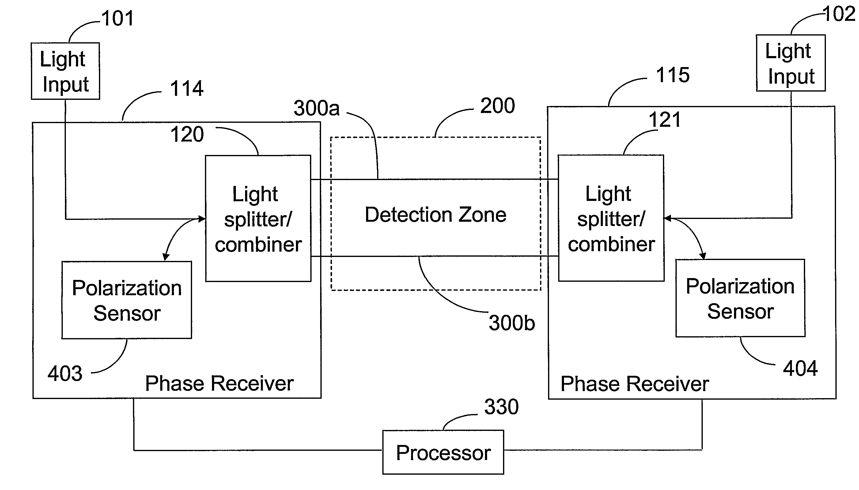
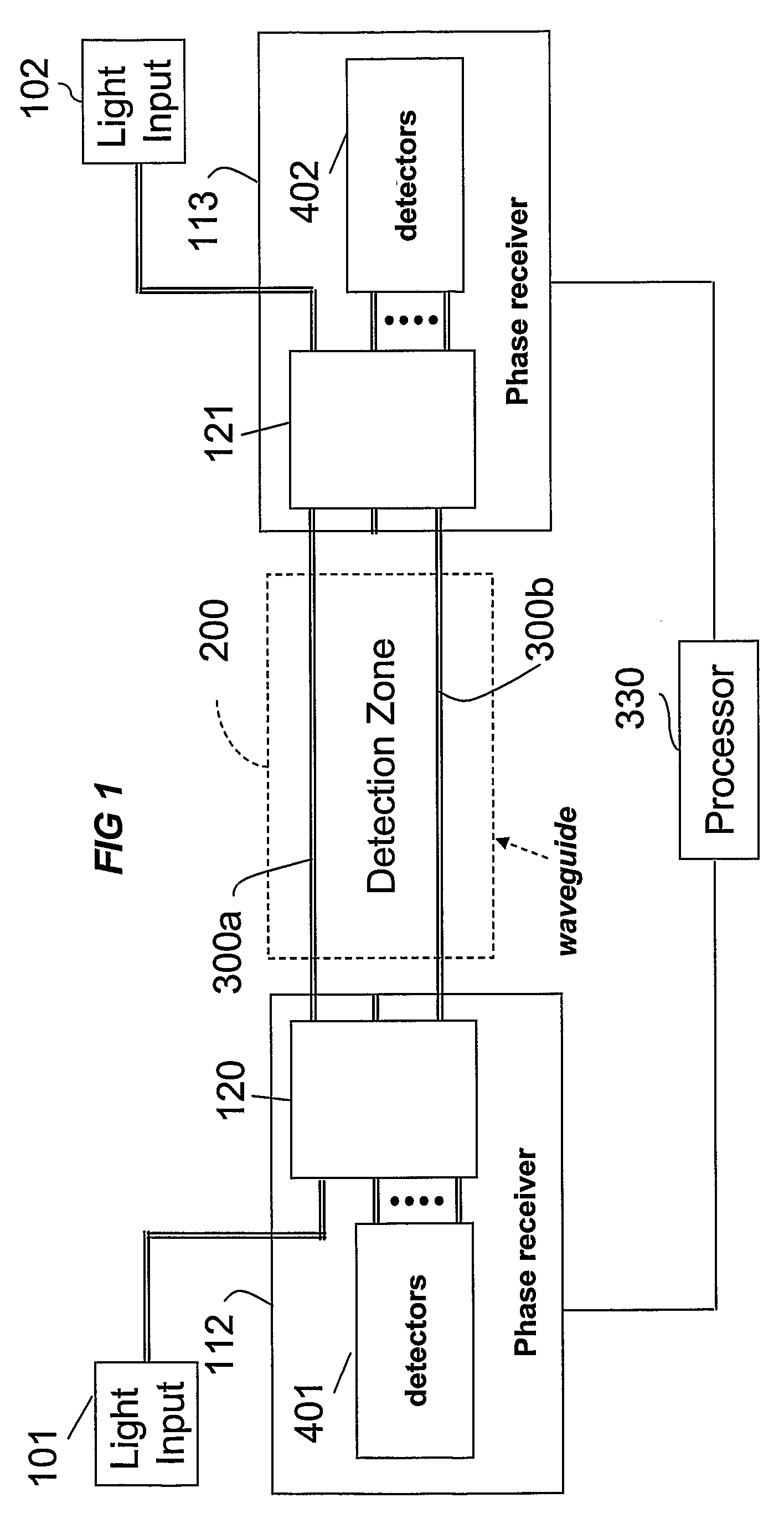
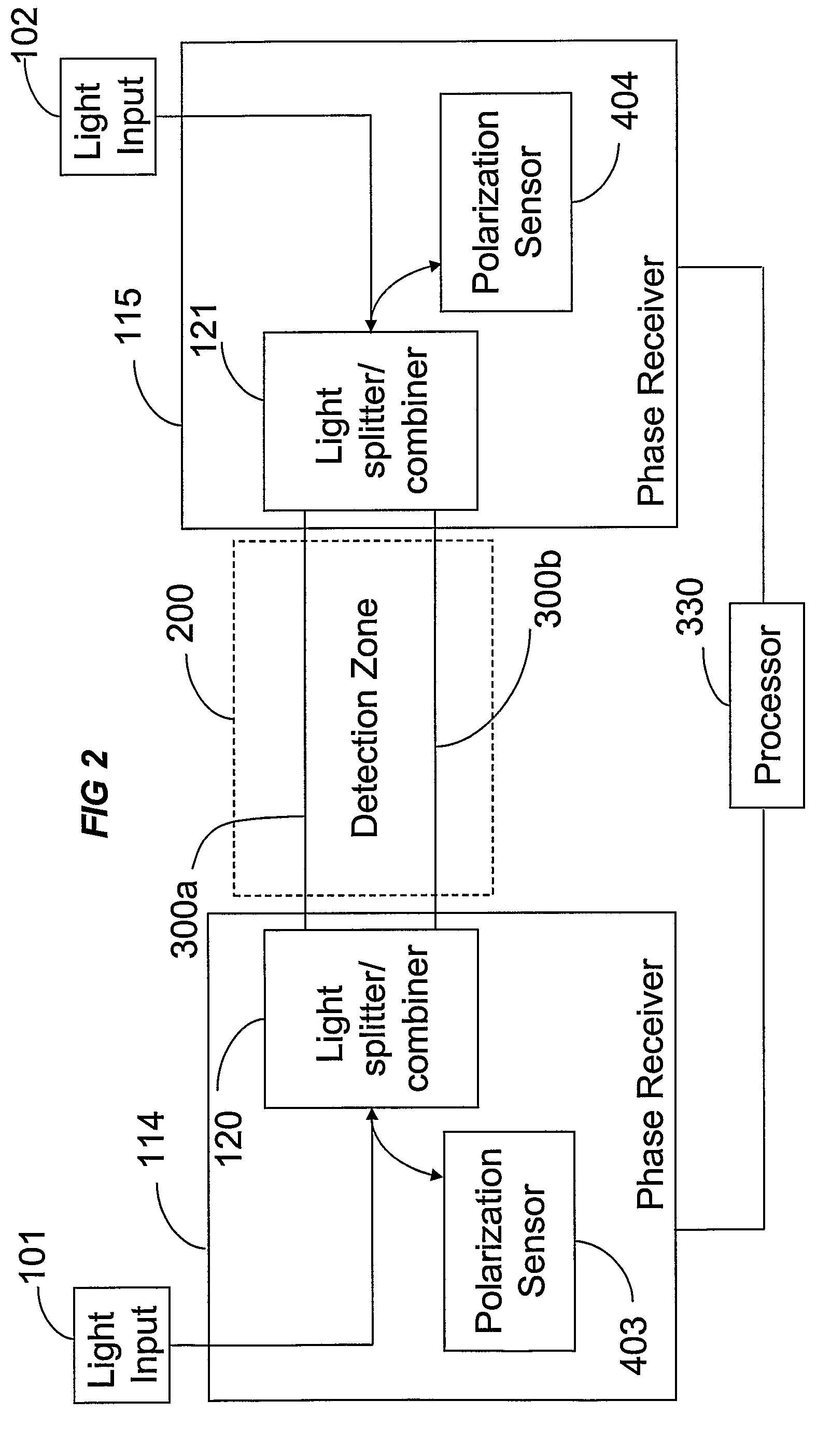
[0122]In this first example, light from the same source is launched into two fibers using a polarization insensitive light splitter. The output light is combined, using a polarization insensitive beam combiner. The combined output light is analyzed using a polarization measurement system (such as a high speed version of PS2300B polarization analyzer available from Optellios, Inc., Langhorne, Pa.) or using another polarization sensitive detector or detection scheme. A detected change of polarization provides information relating to the phase difference between the light signals that travel along the two signal paths for each of the opposite signal directions.
[0123]This approach does not require a particular state of polarization for light signals launched into the fiber(s). Nor is it necessary that the fiber have a particular amount of birefringence. The measurement generally is not influenced by different starting conditions (polarization states...
example 1.2
Polarization Sensitive Beam Combiner
[0138]In this second example, light from the same source is launched into two fibers using a polarization beam splitter, thereby creating two beams. The signal from the same light source can be used to create both counter-propagating beams. The light beams pass through the detection zone and are then combined, using a polarization beam combiner so as to analyze the orthogonal components of the beams in the two fibers. The combined signal is analyzed using a polarimeter or other polarization sensitive detection scheme. The change of polarization provides the information about the phase difference between the beams that travel along the two paths.
[0139]A schematic example demonstrating phase detection based on polarization change is shown in FIG. 8. Light is injected into two paths 300a and 300b by operation of a beam splitter 122 (element A). In the illustrated example, the beam splitter is a polarization beam splitter. Both beams are recombined us...
PUM
| Property | Measurement | Unit |
|---|---|---|
| size | aaaaa | aaaaa |
| wavelength | aaaaa | aaaaa |
| phase relationship | aaaaa | aaaaa |
Abstract
Description
Claims
Application Information
 - R&D
- Intellectual Property
- Life Sciences
- Materials
- Tech Scout
- Unparalleled Data Quality
- Higher Quality Content
- 60% Fewer Hallucinations
Browse by: Latest US Patents, China's latest patents, Technical Efficacy Thesaurus, Application Domain, Technology Topic, Popular Technical Reports.
© 2025 PatSnap. All rights reserved.Legal|Privacy policy|Modern Slavery Act Transparency Statement|Sitemap|About US| Contact US: help@patsnap.com


