
Apparatus and method for tracking movement of a target

a technology of a target and an apparatus, applied in the field of head tracking, can solve the problems of image artifacts, degrade the quality of images, and the presence of moving biological tissue is problemati

Inactive Publication Date: 2009-02-12
VETERANS AFFAIRS US GOVT AS REPRESENTED BY THE DEPT OF +1
View PDF24 Cites 38 Cited by
  • Summary
  • Abstract
  • Description
  • Claims
  • Application Information

AI Technical Summary

Benefits of technology

The patent is about a system that uses a special pattern on a patient's head to track their movement during an MRI scan. The system uses optical systems and a processor to record the pattern and analyze its movement. This information is then fed back to the MRI machine to adjust the focusing coils and make the MRI procedure more accurate. The technical effect is that the MRI procedure becomes more accurate and efficient because it is adjusted for the patient's movements.

Problems solved by technology

The technical problem addressed in this patent text is the need for improved patient movement tracking in medical imaging. Current methods of tracking patient movement using cross-correlation or other techniques are not effective in adverse environments such as high field strength fMRI. The invention aims to provide real-time tracking of a patient's head position in a high field strength fMRI without disrupting the scanning process.

Method used


Image

  • Apparatus and method for tracking movement of a target
  • Apparatus and method for tracking movement of a target
  • Apparatus and method for tracking movement of a target

Examples


Embodiment Construction

[0055]While the making and using of various embodiments of the present invention are discussed in detail below, it should be appreciated that the present invention provides many applicable inventive concepts which can be embodied in a wide variety of specific contexts. The specific embodiments described herein are merely illustrative of specific ways to make and use the invention and do not delimit the scope of the invention.

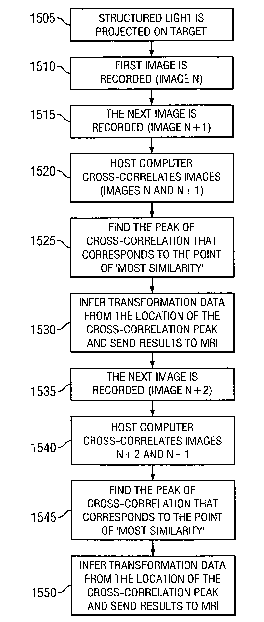
[0056]In one embodiment of the instant invention is a system that is used in conjunction within an MRI machine that uses a predetermined pattern placed or projected onto a patient's head to track movement of a patient during an MRI scan. Optical systems record the position and movement of the pattern and are able to perform mathematical analysis of the pattern to determine the positional shift of the patient.

[0057]In this preferred embodiment, light is projected onto a target that reflects some of the light into an optical receiver. One of the innovations of the...


PUM


Abstract

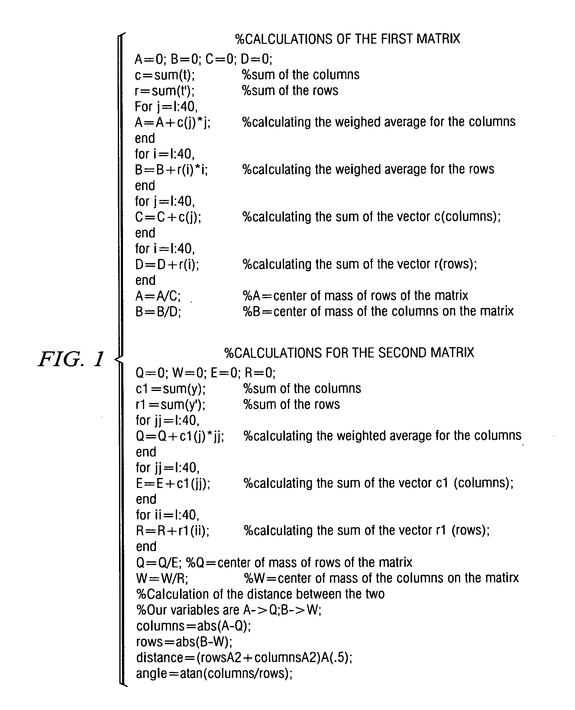
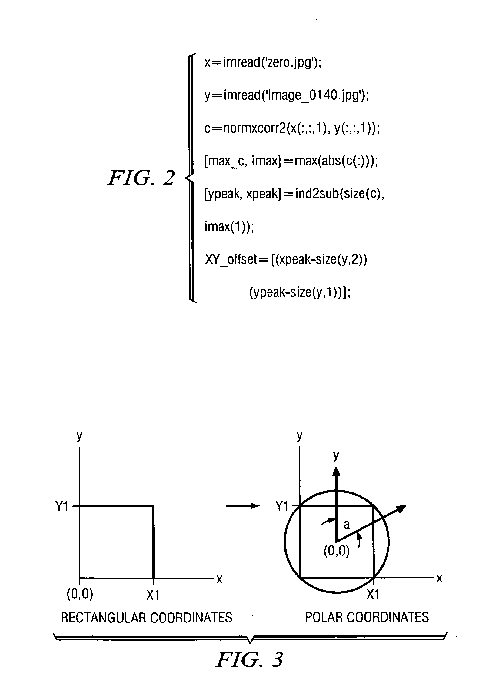
The present invention discloses an apparatus and method to track the movement of a target. One embodiment tracks the movement of the patient during medical imaging scanning using optical technology. Optical systems record the position and movement of the target and provide inputs to a processor. The processor is capable of performing mathematical analysis of the movement of the target to determine the positional shift of the patient. Weighted averages, phase correlation, Fourier-Mellin algorithms, and cross-correlation of data related to X-Y translation are used to calculate movement of the target subject. Feedback related to the movement is provided to the medical imaging scanning machine which allows for adjustments in focusing coils for real time tracking of the patient's movements during the procedure. As a result, the medical image scanning procedure becomes more accurate as it is adjusted for the patient's movements.

Description


Claims


Application Information

Patent Timeline
Owner VETERANS AFFAIRS US GOVT AS REPRESENTED BY THE DEPT OF
Learn More