
Photoresist stripping apparatus, and methods of stripping photoresist and forming thin film pattern using the same

a photoresist and stripping technology, applied in the direction of electrical devices, photomechanical treatment, instruments, etc., can solve the problems of environmental pollution and manufacturing cost increase, and achieve the effect of effectively forming a thin film pattern, and effectively stripping a photoresis

Active Publication Date: 2018-07-19
SAMSUNG DISPLAY CO LTD
View PDF3 Cites 0 Cited by
  • Summary
  • Abstract
  • Description
  • Claims
  • Application Information

AI Technical Summary

Benefits of technology

This patent text provides a method and device for effectively forming a thin film pattern and stripping photoresist. The method and device help reduce environmental pollution and manufacturing costs while ensuring a high-quality thin film pattern.

Problems solved by technology

In general, when a thin film is formed through a photolithography process, a large amount of chemical stripping solutions are used to strip photoresist, such that environmental pollution and manufacturing cost may increase.

Method used


Image

  • Photoresist stripping apparatus, and methods of stripping photoresist and forming thin film pattern using the same
  • Photoresist stripping apparatus, and methods of stripping photoresist and forming thin film pattern using the same
  • Photoresist stripping apparatus, and methods of stripping photoresist and forming thin film pattern using the same

Examples


Embodiment Construction

[0035]The invention now will be described more fully hereinafter with reference to the accompanying drawings, in which various embodiments are shown. This invention may, however, be embodied in many different forms, and should not be construed as limited to the embodiments set forth herein. Rather, these embodiments are provided so that this disclosure will be thorough and complete, and will fully convey the scope of the invention to those skilled in the art. Like reference numerals refer to like elements throughout.

[0036]It will be understood that when an element is referred to as being “on” another element, it can be directly on the other element or intervening elements may be present therebetween. In contrast, when an element is referred to as being “directly on” another element, there are no intervening elements present.

[0037]It will be understood that, although the terms “first,”“second,”“third” etc. may be used herein to describe various elements, components, regions, layers a...


PUM

PropertyMeasurementUnit
voltageaaaaaaaaaa
voltageaaaaaaaaaa
packing densityaaaaaaaaaa

Abstract

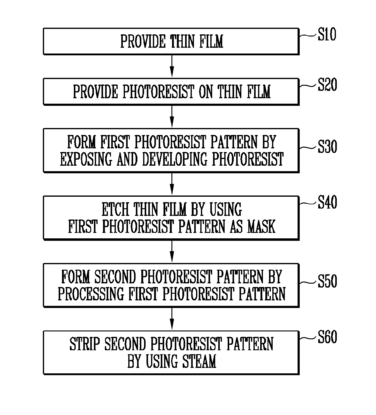
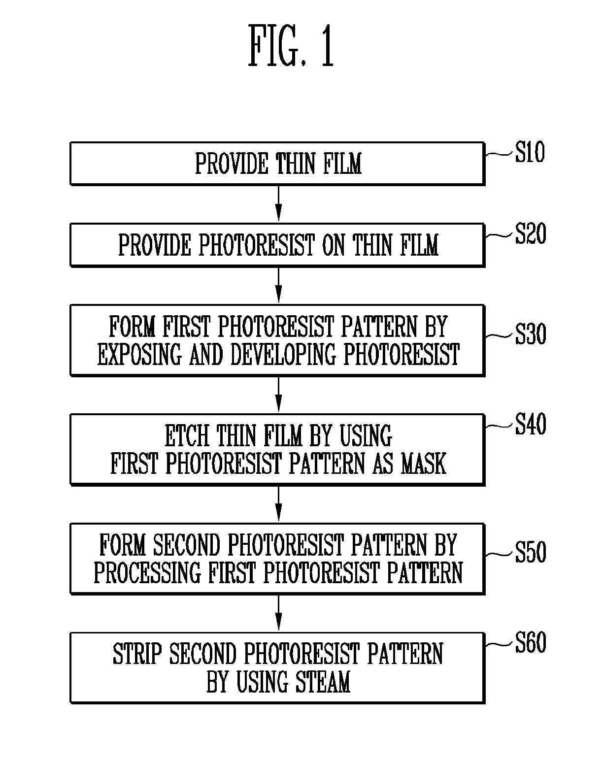
A method of forming a thin film pattern includes providing a thin film on a substrate, providing a photoresist on the thin film, forming a first photoresist pattern having a first packing density by exposing and developing the photoresist, etching the thin film by using the first photoresist pattern as a mask, processing the first photoresist pattern to convert the first photoresist pattern into a second photoresist pattern having a second packing density, which is lower than the first packing density, and stripping the second photoresist pattern by spraying steam onto the second photoresist pattern.

Description

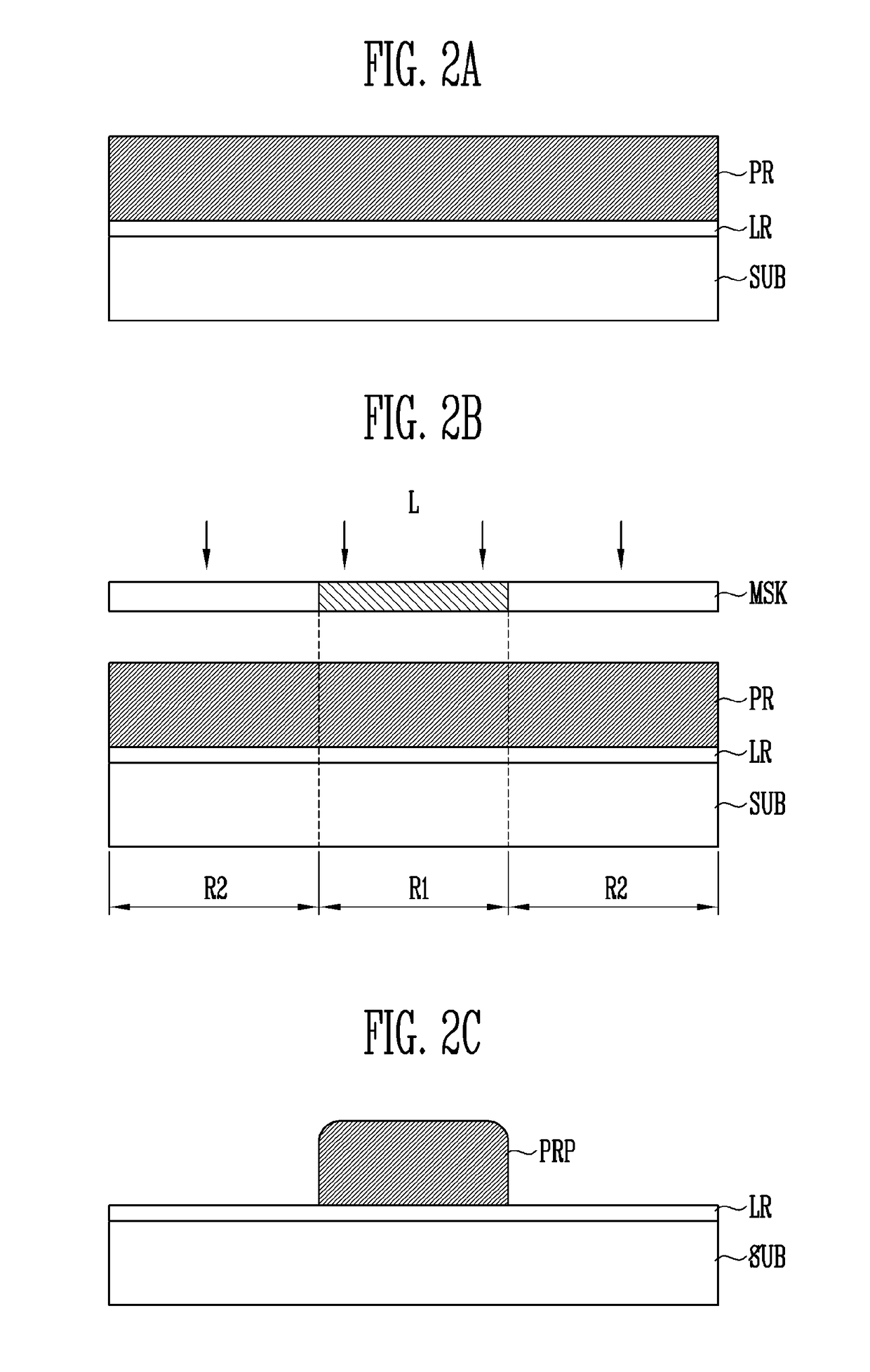
[0001]This application claims priority to Korean Patent Application No. 10-2017-0007112, filed on Jan. 16, 2017, and all the benefits accruing therefrom under 35 U.S.C. § 119, the content of which in its entirety is herein incorporated by reference.BACKGROUND1. Field[0002]Exemplary embodiments of the disclosure relate to a photoresist stripping apparatus, and a method of stripping photoresist and forming thin film pattern using the photoresist stripping apparatus.2. Description of the Related Art[0003]In general, a process of forming a thin film pattern is used to fabricate an electronic element such as a semiconductor element. A thin film may be formed through a photolithography process. Photolithography is performed in a form of forming a thin film and photoresist on a substrate to be processed, exposing and developing the photoresist, etching the thin film which becomes a target by using the photoresist as a mask, and stripping the photoresist.SUMMARY[0004]In general, when a thin...

Claims


Application Information

Patent Timeline
Patent Type & Authority Applications(United States)
IPC IPC(8): G03F7/42H01L21/027H01L21/3213H01L21/47H01L21/033
CPCG03F7/42H01L21/0273H01L21/0332H01L21/47H01L21/32139H01L21/02697H01L21/027H01L21/0272H01L21/0331H01L21/31133G03F7/427G03F7/34G03F7/30G03F7/20
Inventor JEONG, BEUNG HWACHOUNG, JONG HYUNKIM, SUNG CHUL
Owner SAMSUNG DISPLAY CO LTD
Learn More