Method for operating a supply assembly for supplying fuel gas and inert media to a gas turbine combustor, such supply assembly and a gas turbine comprising such supply assembly

a technology of gas turbine combustor and supply assembly, which is applied in the direction of turbine/propulsion fuel valve, turbine/propulsion fuel flow conduit, combustion process, etc., can solve the problems of high nox emission level, affecting the stability of the combustor, and damage to the gas turbine hardware, so as to reduce the flow rate of inert purge media

Active Publication Date: 2018-07-05
ANSALDO ENERGIA SWITZERLAND AG
View PDF0 Cites 1 Cited by
  • Summary
  • Abstract
  • Description
  • Claims
  • Application Information

AI Technical Summary

Benefits of technology

The invention is a control system for a gas turbine that can smoothly transfer between different fuels without causing sudden temperature changes or exposing gas turbine hardware to high temperatures. The control system achieves this by starting a temporally parallel supply of fuel gas and inert purge media and then reducing the fuel gas flow rate and stopping the fuel gas supply. This allows for a smooth transition to the inert purge media supply and ensures a stable gas turbine operation. The technical effect of this invention is to prevent damage and improve the efficiency of gas turbines during start-up and maintenance procedures.

Problems solved by technology

However, due to this high temperature, high NOx emission levels are generated.
Unfortunately, today the transfer from the fuel gas to the inert purge media operation affects the combustor stability.
The resulting sudden heat release can damage the gas turbine hardware up to conditions that fuel gas leakages occur.

Method used


Image

  • Method for operating a supply assembly for supplying fuel gas and inert media to a gas turbine combustor, such supply assembly and a gas turbine comprising such supply assembly
  • Method for operating a supply assembly for supplying fuel gas and inert media to a gas turbine combustor, such supply assembly and a gas turbine comprising such supply assembly
  • Method for operating a supply assembly for supplying fuel gas and inert media to a gas turbine combustor, such supply assembly and a gas turbine comprising such supply assembly

Examples


Embodiment Construction

[0050]In cooperation with attached drawings, the technical contents and detailed description of the present invention are described thereinafter according to preferred embodiments, being not used to limit its executing scope. Any equivalent variation and modification made according to appended claims is all covered by the claims claimed by the present invention.

[0051]Reference will now be made to the drawing figures to describe the present invention in detail.

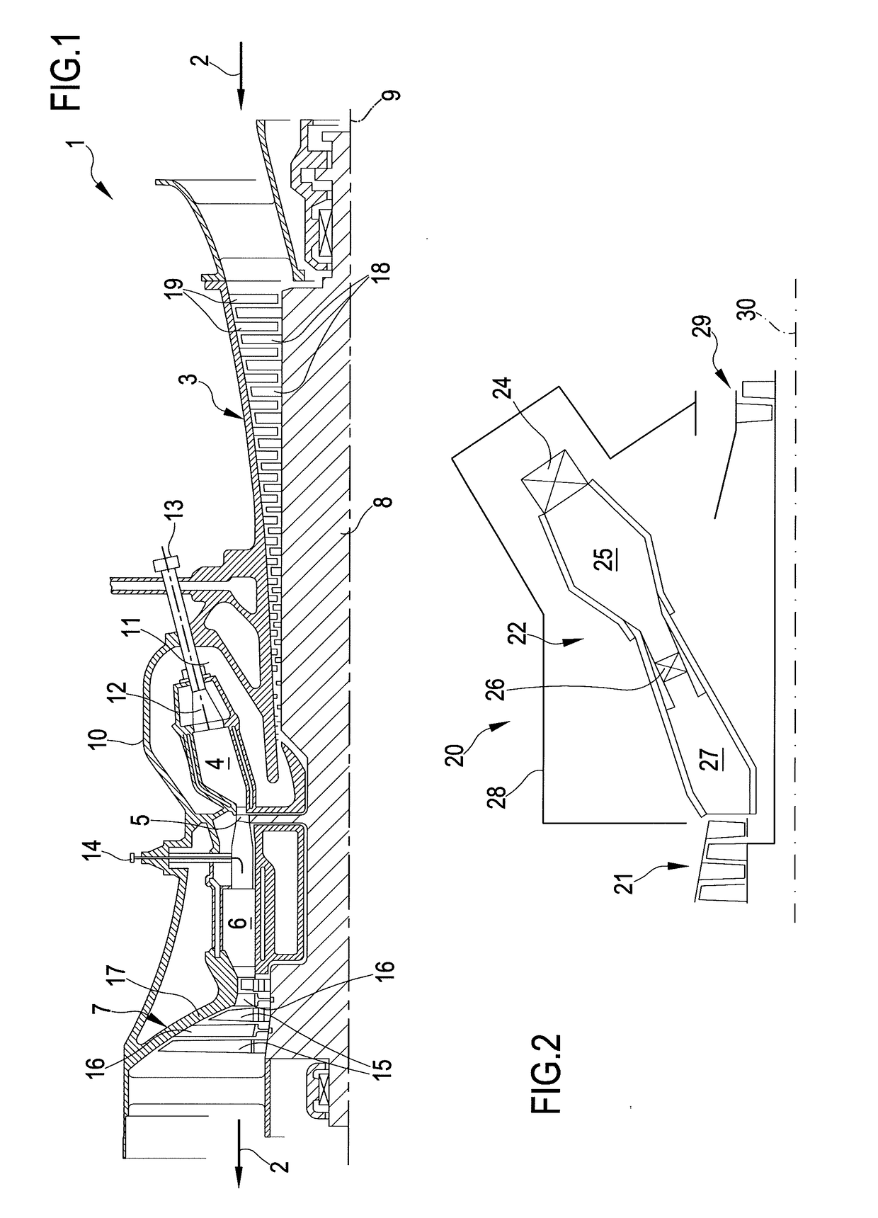
[0052]Reference is now made to FIG. 1 that is a schematic view of a first example of a sequential gas turbine 1 that can be provided with a supply assembly according to the invention. In particular, FIG. 1 discloses a sequential gas turbine with a high pressure and a low pressure turbine.

[0053]Following the main gas flow 2, the gas turbine 1 comprises a compressor 3, a first combustion chamber 4, a high-pressure turbine 5, a second combustion chamber 6 and a low-pressure turbine 7. The compressor 3 and the two turbines 5, 7 are...


PUM


Abstract

A method for operating a supply assembly configured for supplying fuel gas and an inert purge media to a gas turbine combustor, the method including supplying fuel gas in a fuel gas circuit with an upper flow rate; reducing the fuel gas flow rate in the fuel gas circuit from the upper flow rate to a lower flow rate; stopping the supply of the fuel gas in the fuel gas circuit; and starting the supply of the inert purge media in the inert purge media circuit, wherein the starting is performed before the stopping to have a temporary parallel supply of fuel gas and of inert purge media to a fuel distribution system.

Description

PRIORITY CLAIM[0001]This application claims priority from European Patent Application No. 16207566.7 filed on Dec. 30, 2016, the disclosure of which is incorporated by reference.FIELD OF THE INVENTION[0002]The present invention relates to a method for operating a supply assembly configured for supplying fuel gas and an inert media as a purge flow to a gas turbine combustor, in particular to a plurality of can combustors.[0003]Moreover, the present invention relates to a supply assembly configured for performing the above mentioned method and to a gas turbine comprising such supply assembly.DESCRIPTION OF PRIOR ART[0004]As known, a gas turbine power plant (in the following only gas turbine) comprises a rotor provided with an upstream compressor, at least a combustion chamber and at least a downstream turbine. The terms “downstream” and “upstream” refer to the direction of the main gas flow passing through the gas turbine from the compressor to the turbine. In particular, the compress...

Claims


Application Information

Patent Timeline
IPC IPC(8): F02C9/40F02C3/30F02C7/232
CPCF02C9/40F02C3/30F02C7/232F02C3/04F05D2220/32F05D2240/35F05D2260/602F23R3/02F23R3/28F01D21/00F02C9/26F05D2270/31F02C7/222
Inventor SCHELL, SUSANNE RENATELIEBAU, MARTIN
Owner ANSALDO ENERGIA SWITZERLAND AG
Why Eureka
Try Eureka