
System and method of heat management for vehicle

a technology of heat management and vehicle, applied in the direction of engine starters, electric control, machines/engines, etc., can solve the problems of thermal efficiency decline, thermal deformation, and deterioration of the lubrication action between the piston and the cylinder block, so as to improve engine output and efficiency, the effect of rapid increase of the temperature of the coolan

Inactive Publication Date: 2018-06-07
HYUNDAI MOTOR CO LTD +1
View PDF11 Cites 5 Cited by
  • Summary
  • Abstract
  • Description
  • Claims
  • Application Information

AI Technical Summary

Benefits of technology

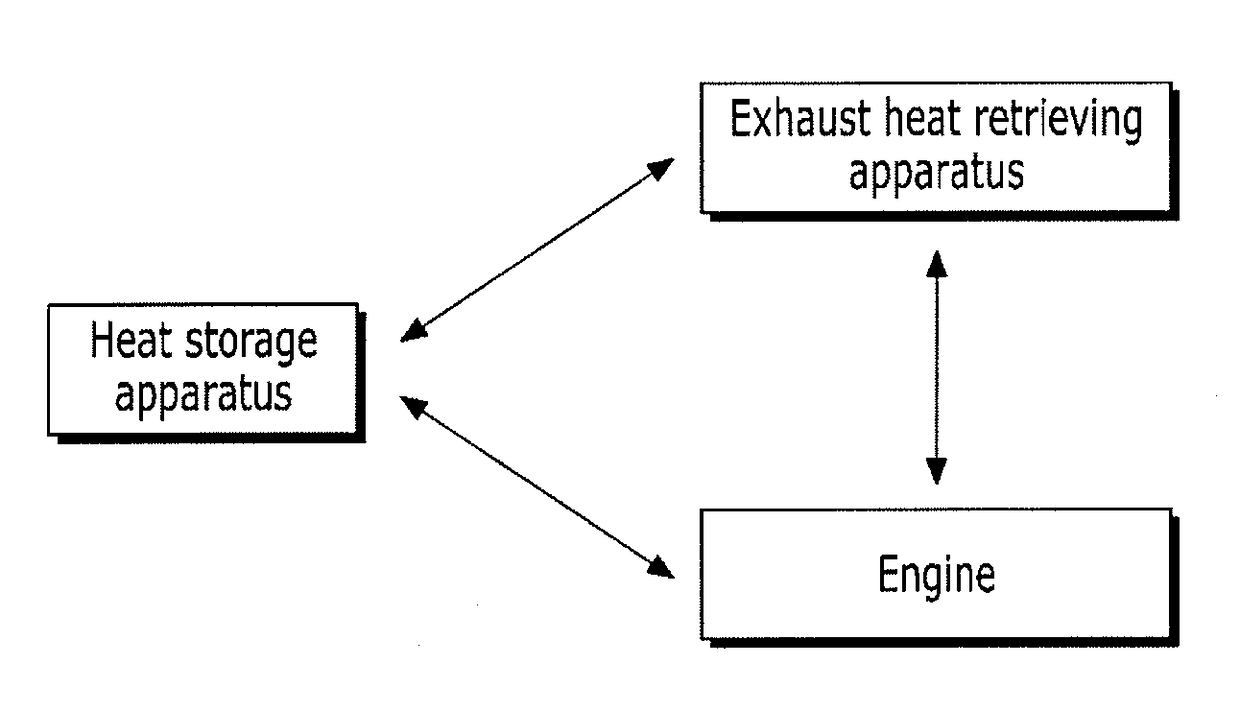
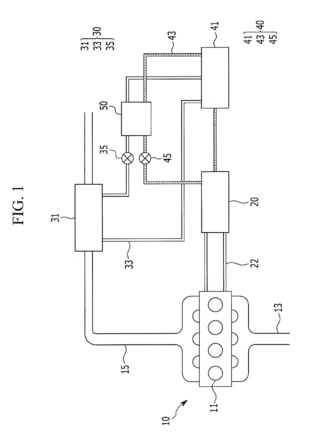
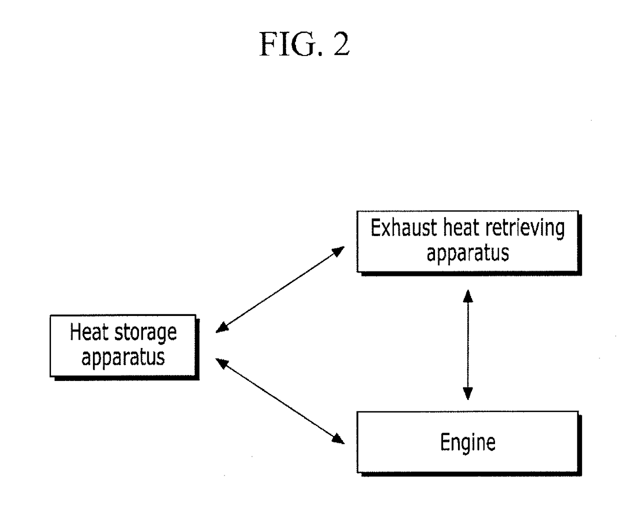
The present invention provides a system for managing heat in a vehicle to improve engine output and efficiency by quickly increasing the temperature of the coolant when the engine is started. Additionally, the system is designed to improve fuel efficiency by controlling coolant temperature based on the driving region of the engine. This is achieved through the use of an exhaust heat retrieving apparatus and a heat storage apparatus, which allow for rapid coolant temperature adjustments and improved engine performance.

Problems solved by technology

When a temperature of these components is excessively increased, thermal deformation is generated in the respective components formed of a metal material or an oil film of a cylinder inner wall is damaged, such that a thermal fault that a lubrication action between the piston and the cylinder block deteriorates occurs.
This thermal fault phenomenon of the engine generates abnormal combustion such as a combustion defect, knocking, pre-ignition, or the like, of the engine, decreases thermal efficiency, and decreases an output of the engine.
To the contrary, when a temperature of a coolant of the engine is excessively decreased, an output of the engine and fuel consumption are decreased.
In addition, since a temperature of the combustion chamber is low, an excessive amount of exhaust gas is emitted due to incomplete combustion.

Method used


Image

  • System and method of heat management for vehicle
  • System and method of heat management for vehicle
  • System and method of heat management for vehicle

Examples


Embodiment Construction

[0036]Reference will now be made in detail to various embodiments of the present invention(s), examples of which are illustrated in the accompanying drawings and described below. While the invention(s) will be described in conjunction with exemplary embodiments, it will be understood that the present description is not intended to limit the invention(s) to those exemplary embodiments. On the contrary, the invention(s) is / are intended to cover not only the exemplary embodiments, but also various alternatives, modifications, equivalents and other embodiments, which may be included within the spirit and scope of the invention as defined by the appended claims.

[0037]A description for contents that are not associated with the present invention will be omitted to clearly describe the present invention, and like reference numerals designate like elements throughout the specification.

[0038]In addition, since sizes and thicknesses of the respective components were arbitrarily shown in the ac...


PUM


Abstract

A system of heat management of a vehicle may include a cooling line in which coolant cooling an engine flows therethrough; an exhaust heat retrieving apparatus for retrieving heat of exhaust gas discharged from a combustion chamber of the engine through operation fluid; a heat storage apparatus which stores heat of exhaust gas retrieved by the exhaust heat retrieving apparatus using the operation fluid and includes phase change material; a coolant heat exchanger in which heat stored in the heat storage apparatus and the coolant are heat-exchanged; a driving information detector for detecting a driving information including a temperature of the coolant and a temperature of the phase change material; and a controller for controlling the temperature of the coolant through the exhaust heat retrieving apparatus or the heat storage apparatus based on the temperature of the coolant and the temperature of the phase change material when the vehicle starts.

Description

CROSS-REFERENCE TO RELATED APPLICATION[0001]The present application claims priority to Korean Patent Application No. 10-2016-0165929 filed on Dec. 7, 2016, the entire contents of which is incorporated herein for all purposes by this reference.BACKGROUND OF THE INVENTIONField of the Invention[0002]The present invention relates to a system and a method of heat management of a vehicle.Description of Related Art[0003]Generally, some of heat generated in a combustion chamber of an engine is transferred to a cylinder head, a cylinder block, a piston, and the like.[0004]When a temperature of these components is excessively increased, thermal deformation is generated in the respective components formed of a metal material or an oil film of a cylinder inner wall is damaged, such that a thermal fault that a lubrication action between the piston and the cylinder block deteriorates occurs.[0005]This thermal fault phenomenon of the engine generates abnormal combustion such as a combustion defect...

Claims


Application Information

Patent Timeline
Patent Type & Authority Applications(United States)
IPC IPC(8): F02D41/06F02N19/10
CPCF02D41/068F02D2200/021F02D41/064F02N19/10F01N5/02F01P11/00F02D2200/023
Inventor KIM, HAN SANGPARK, JUNGJOOCHOI, CHOO SAENG
Owner HYUNDAI MOTOR CO LTD
Learn More