
Method of fabricating nanoporous metal structure

a nanoporous metal and metal structure technology, applied in the direction of cell components, vacuum evaporation coatings, coatings, etc., can solve the problems of low efficiency, poor stability of the catalyst, and commercialization of dm

Active Publication Date: 2018-05-24
CITY UNIVERSITY OF HONG KONG
View PDF4 Cites 7 Cited by
  • Summary
  • Abstract
  • Description
  • Claims
  • Application Information

AI Technical Summary

Benefits of technology

The present invention relates to a method of fabricating a nanoporous metal structure and to a fuel cell including such a structure. This method involves providing a piece of first alloy containing at least a first metal (such as gold, palladium, or platinum) and a second metal, and then chemically removing some of the second metal from the first alloy to create a nanoporous metal substrate. These nanoporous metal structures have many small pores that make them ideal for use in fuel cells. The technical effects of this invention include improved fuel cell performance and more efficient production of nanoporous metal structures.

Problems solved by technology

However, two key issues limit the commercialization of DMFC, the first being low efficiency and the second being the poor stability of its catalyst.
Platinum (Pt) is the most popular catalyst for anode and cathode for use in DMFC, but Pt is an expensive noble metal and is easily poisoned by carbonaceous intermediates, leading to the reduction of catalytic stability.
However, Pd or Pd-based component catalysts may also exhibit poor stability if they suffer from the same “poisoning effect” as Pt.
However, black carbon becomes unstable after several cycles of electro-oxidation reaction.

Method used


Image

  • Method of fabricating nanoporous metal structure
  • Method of fabricating nanoporous metal structure
  • Method of fabricating nanoporous metal structure

Examples


Embodiment Construction

[0062]Nanoporous metals, such as gold (Au), palladium (Pd) and platinum (Pt), have been attracting increasing attention for their wide variety of applications in functional areas. Porous structure is especially ideal for catalytic applications because of the large surface-to-volume ratio as well as the interconnected channels and metal ligaments, which accelerate the transportation of electrons and molecules, thus providing excellent electrical conductivity. For this reason, several approaches have been developed to fabricate nanoporous metals. Chemical dealloying and electrochemical dealloying are both regarded as being effective approaches through which the more electrochemically active metal is dissolved and the more noble metal remains.

[0063]There are two key principles relating to dealloying processes, namely the limiting principle and the critical potential for electrochemical dealloying. The limiting principle states that the atomic fraction of the less noble metal must be mo...


PUM

PropertyMeasurementUnit
thicknessaaaaaaaaaa
thicknessaaaaaaaaaa
distanceaaaaaaaaaa

Abstract

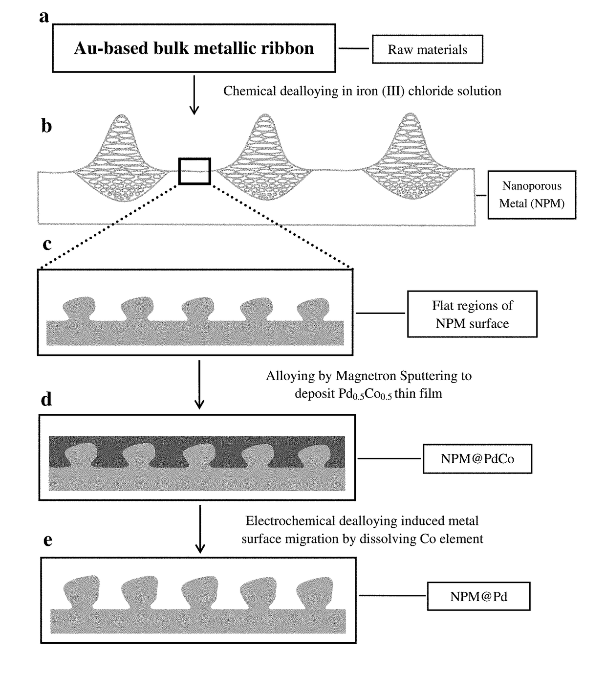
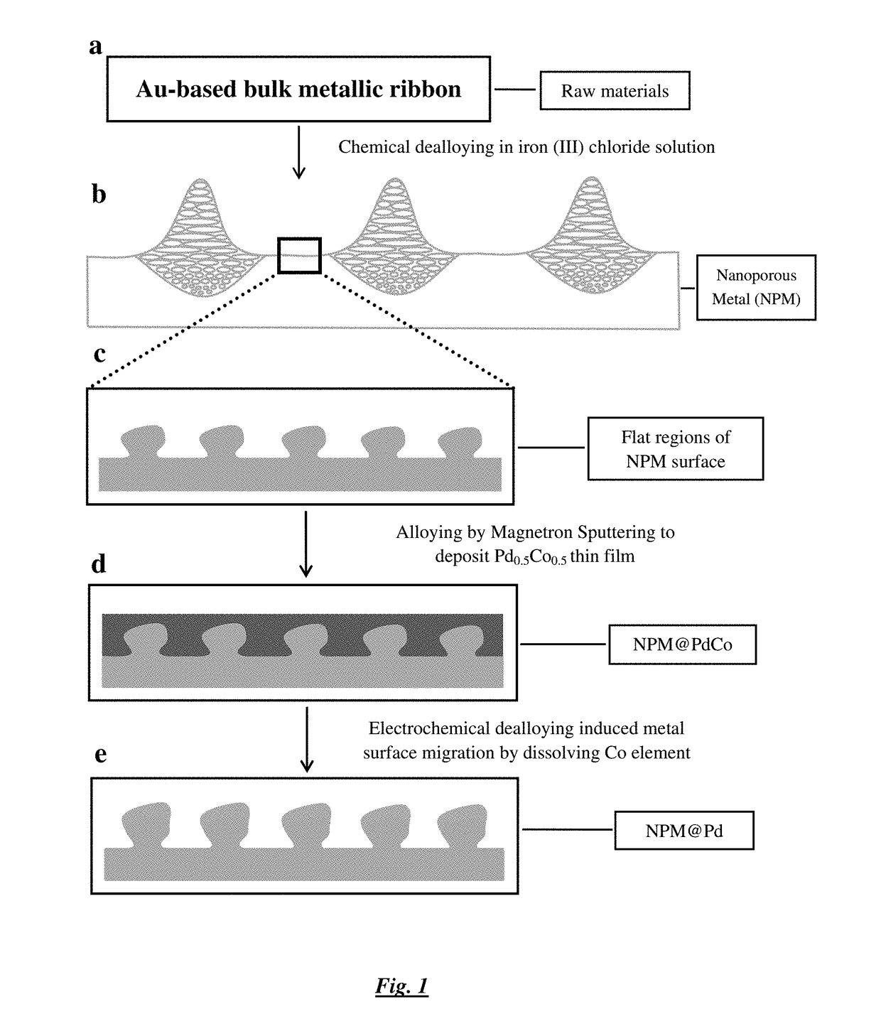
A method of fabricating a nanoporous metal structure, such as a nanoporous metal (NMP) supported Pd catalyst suitable for use in a direct methanol fuel cell (DMFC), is includes the steps of (a) providing a piece of Au55Cu25Si20 alloy glass ribbon with a thickness of 50 μm, (b) dealloying the piece of alloy glass ribbon by reacting with iron (III) chloride solution to form a free-standing NPM ribbon, (c) depositing a thin film of PdCo of a thickness of 100 nm on the NPM ribbon by RF magnetron sputtering with Pd0.5Co0.5 (atomic percent) as target in an argon atmosphere, and (d) electrochemically dissolving some of the Co on the thin film of PdCo to induce migration of Au from the NPM ribbon to the thin layer of PdCo.

Description

[0001]This invention relates to a method of fabricating nanoporous metal structure suitable for use in, but not limited to, direct methanol fuel cells (DMFC), e.g. as a catalyst.BACKGROUND OF THE INVENTION[0002]A fuel cell is an energy conversion device that converts chemical energy into electricity, and a proton exchange membrane fuel cell (PEMFC) operating at a low temperature has been receiving more and more attention. Because of the difficulty of hydrogen storage associated with PEMFC, direct methanol fuel cells (DMFC) and direct ethanol fuel cell (DEFC) are known to be more advantageous than PEMFC. However, two key issues limit the commercialization of DMFC, the first being low efficiency and the second being the poor stability of its catalyst.[0003]Platinum (Pt) is the most popular catalyst for anode and cathode for use in DMFC, but Pt is an expensive noble metal and is easily poisoned by carbonaceous intermediates, leading to the reduction of catalytic stability. For this rea...

Claims


Application Information

Patent Timeline
Patent Type & Authority Applications(United States)
IPC IPC(8): H01M4/92C23C14/16H01M4/88
CPCH01M4/925C23C14/35H01M4/8871C23C14/165Y02E60/50C22C45/003C25F3/02
Inventor XU, YIYIU, PAK MANSHEK, CHAN HUNG
Owner CITY UNIVERSITY OF HONG KONG
Learn More