Methods and spoke supports for additive manufacturing

a technology of additive manufacturing and spoke supports, which is applied in the direction of additive manufacturing, process efficiency improvement, additive manufacturing apparatus, etc., can solve the problems of bending or warping of vertical members, complex process, and low understanding of the science and technical aspects of the production route, so as to maintain the dimensional stability of the object

Inactive Publication Date: 2018-05-24
GENERAL ELECTRIC CO
View PDF4 Cites 7 Cited by
  • Summary
  • Abstract
  • Description
  • Claims
  • Application Information

AI Technical Summary

Benefits of technology

The patent describes a method for making objects using a laser to fuse powder layers. There are several benefits that come from this method: the first is that it allows for the creation of objects that have a support structure, which helps to maintain their shape during heat treatment and machining. The second is that the laser can create a strong bond between the support structure and the object, making it difficult for the support structure to break or deform during heat treatment. The method can also create objects with a unique structure and shape, allowing for the fabrication of complex objects.

Problems solved by technology

Although the laser sintering and melting processes can be applied to a broad range of powder materials, the scientific and technical aspects of the production route, for example, sintering or melting rate and the effects of processing parameters on the microstructural evolution during the layer manufacturing process have not been well understood.
This method of fabrication is accompanied by multiple modes of heat, mass and momentum transfer, and chemical reactions that make the process very complex.
In particular, thermal expansion during the heat treatment may result in bending or warping of the vertical members 202.
For parts with tight manufacturing tolerances, the deformation may result in an unacceptable part.
For example, in a fuel nozzle application, deformation may result in parts being misaligned.

Method used


Image

  • Methods and spoke supports for additive manufacturing
  • Methods and spoke supports for additive manufacturing
  • Methods and spoke supports for additive manufacturing

Examples


Embodiment Construction

[0020]The detailed description set forth below in connection with the appended drawings is intended as a description of various configurations and is not intended to represent the only configurations in which the concepts described herein may be practiced. The detailed description includes specific details for the purpose of providing a thorough understanding of various concepts. However, it will be apparent to those skilled in the art that these concepts may be practiced without these specific details. In some instances, well known components are shown in block diagram form in order to avoid obscuring such concepts.

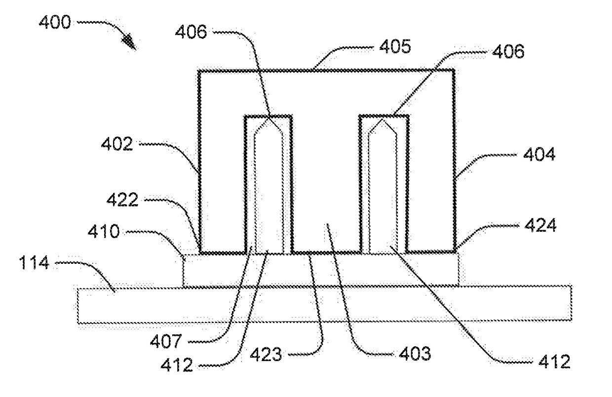
[0021]FIG. 4 illustrates an example of an object 400 supported by a spoke support 410. Similar to the object 200, the object 400 includes multiple vertical members 402, 403, 404 which may include, for example, legs or annular walls. The vertical members 402, 403, 404 are connected by a top portion 405. Each of the vertical members 402, 403, 404 includes a respective dist...


PUM

PropertyMeasurementUnit
Angleaaaaaaaaaa
Distanceaaaaaaaaaa
Dimensional stabilityaaaaaaaaaa

Abstract

The present disclosure generally relates to methods for additive manufacturing (AM) that utilize spoke support structures in the process of building objects, as well as novel spoke support structures to be used within these AM processes. The object includes a first portion and a second portion. A first distal end of the first portion is separated from a second distal end of the second portion by a portion of unfused powder. At least one support structure connects the first distal end to the second distal end. The method includes removing the object and the support structure from the powder bed. The method includes heat treating the object and the support structure. The support structure maintains dimensional stability of the object during the heat treatment. The method includes machining away the support structure from the first distal end and the second distal end after the heat treatment.

Description

INTRODUCTION[0001]The present disclosure generally relates to methods for additive manufacturing (AM) that utilize support structures in the process of building objects, as well as novel support structures to be used within these AM processes.BACKGROUND[0002]AM processes generally involve the buildup of one or more materials to make a net or near net shape (NNS) object, in contrast to subtractive manufacturing methods. Though “additive manufacturing” is an industry standard term (ASTM F2792), AM encompasses various manufacturing and prototyping techniques known under a variety of names, including freeform fabrication, 3D printing, rapid prototyping / tooling, etc. AM techniques are capable of fabricating complex components from a wide variety of materials. Generally, a freestanding object can be fabricated from a computer aided design (CAD) model. A particular type of AM process uses an energy beam, for example, an electron beam or electromagnetic radiation such as a laser beam, to si...

Claims


Application Information

Patent Timeline
IPC IPC(8): B22F3/105B22F3/24B33Y10/00
CPCB22F3/1055B22F3/24B22F2003/247B22F2003/1058B22F2003/248B33Y10/00B22F2998/10Y02P10/25B22F10/28B22F10/64B22F10/47
Inventor FIELDMAN, ZACHARY DAVIDHALL, CHRISTOPHER
Owner GENERAL ELECTRIC CO
Why Eureka
Try Eureka