
Controller for Vehicle

Active Publication Date: 2018-02-01
TOYOTA JIDOSHA KK
View PDF0 Cites 0 Cited by
  • Summary
  • Abstract
  • Description
  • Claims
  • Application Information

AI Technical Summary

Benefits of technology

The patent describes a controller that can decrease the heat load on friction materials in a vehicle transmission and prevent delays or reduction in efficiency when shifting gears. This is achieved by identifying which friction materials are responsible for controlling the rotation of the gear shifts and adjusting the delay time accordingly to minimize the impact on the driver's experience. The controller can also reduce the likelihood of increased heat load and delay while performing an upshift by avoiding the use of certain friction materials. Overall, this technology improves the efficiency and smoothness of shifting gears in vehicles.

Problems solved by technology

Accordingly, when the delay time is excessive, there is concern that a decrease in drivability due to hesitation will occur.

Method used


Image

  • Controller for Vehicle
  • Controller for Vehicle
  • Controller for Vehicle

Examples


Embodiment Construction

[0018]Hereinafter, embodiments of the disclosure will be described with reference to the accompanying drawings.

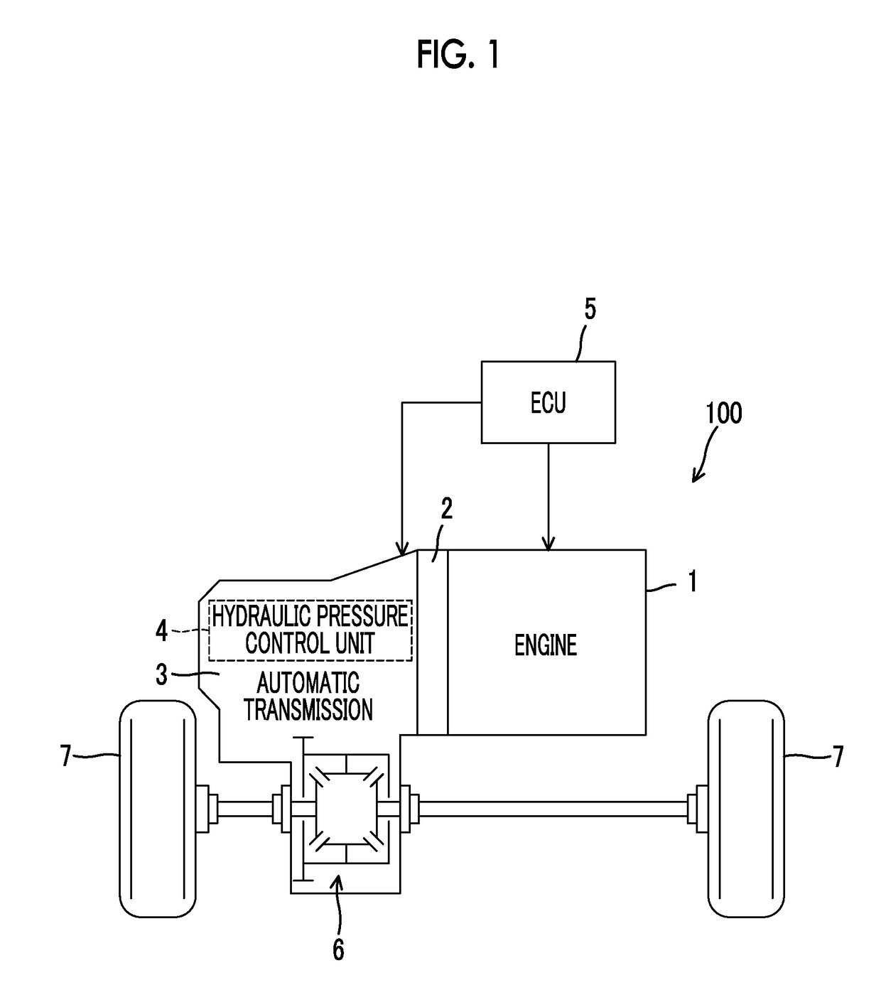
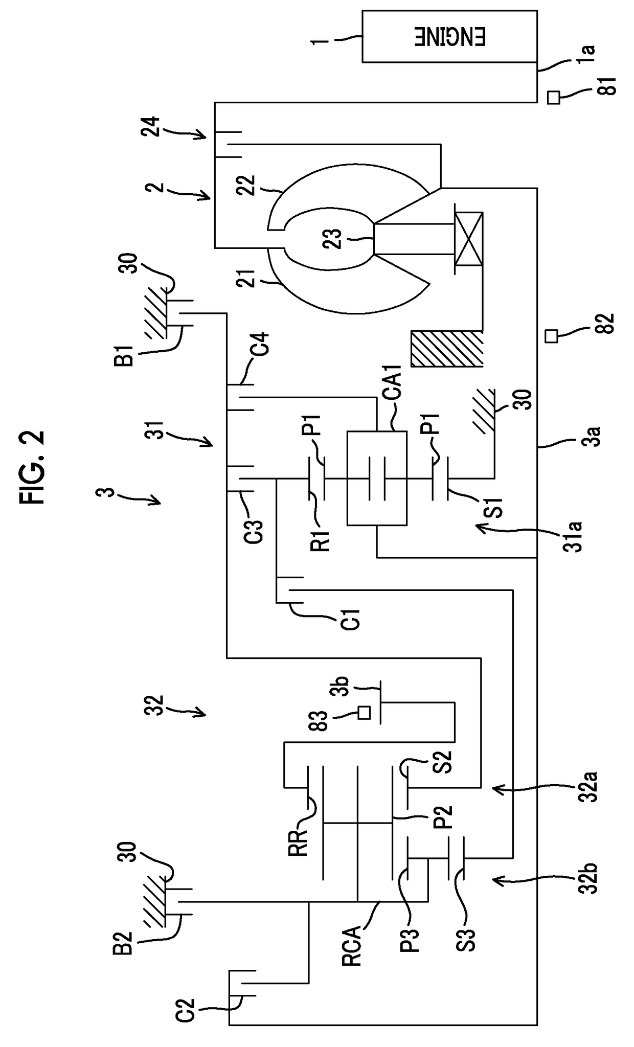
[0019]First, a vehicle 100 according to an embodiment will be described below with reference to FIGS. 1 to 4.

[0020]As illustrated in FIG. 1, the vehicle 100 includes an engine 1, a torque converter 2, an automatic transmission 3, a hydraulic pressure control unit 4, and an electronic control unit (ECU) 5. The vehicle 100 is, for example, of a front engine-front drive (FF) type and is configured such that an output of the engine 1 is transmitted to a differential device 6 via the torque converter 2 and the automatic transmission 3 and is assigned to right and left driving wheels (front wheels) 7.

[0021]—Engine— The engine (internal combustion engine) 1 is a driving force source for traveling and is, for example, a multi-cylinder gasoline engine. The engine 1 is configured such that an operation state thereof can be controlled based on a throttle opening level (an amount of in...


PUM


Abstract

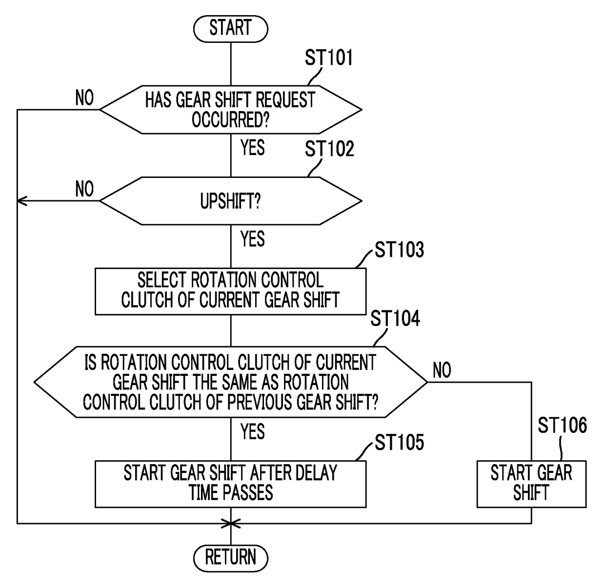
When an engagement-side clutch taking charge of rotation control in an upshift is the same as a rotation control clutch of a previous gear shift, it is determined that there is a likelihood that a thermal load of a clutch friction material will increase, and the thermal load of the clutch friction material is decreased by delaying gear shift start. By setting a delay time by which the gear shift start is delayed when an accelerator depression amount is small to be shorter than when the accelerator depression amount is large depending on the accelerator depression amount, a gear shift which is an upshift can be performed without unnecessary waiting.

Description

INCORPORATION BY REFERENCE[0001]The disclosure of Japanese Patent Application No. 2016-146672 filed on Jul. 26, 2016 including the specification, drawings and abstract is incorporated herein by reference in its entirety.BACKGROUND1. Technical Field[0002]The disclosure relates to a controller for a vehicle including an engine and a stepped transmission2. Description of Related Art[0003]A technique of considering a thermal load on a plurality of frictional engagement elements and the like in a stepped transmission including the plurality of frictional engagement elements is described in Japanese Patent Application Publication No. 2008-101705 (JP 2008-101705 A).[0004]In the technique described in JP 2008-101705 A, a gear shift controller that controls selective engagement of the plurality of frictional engagement elements to perform gear shift control of the transmission includes a calculation unit that calculates a temperature of the frictional engagement elements to be engaged at the...

Claims


Application Information

Patent Timeline
IPC IPC(8): F16H61/02
CPCF16H61/0213F16H2200/2097F16H3/666F16H59/18F16H2200/2046F16H2200/201F16H2200/006F16H61/0262F16H61/04F16H61/08F16H61/16B60Y2300/186B60Y2300/428
Inventor TSUKAMOTO, NORIHIROASAMI, TOMOHIROOTA, KEISUKE
Owner TOYOTA JIDOSHA KK
Learn More