Low dropout regulator circuit and method for controlling a voltage of a low dropout regulator circuit

a low dropout regulator and low dropout current technology, applied in the direction of electric variable regulation, process and machine control, instruments, etc., can solve the problems of low quiescent current consumption of existing ldo circuits, difficult to achieve good transient load performance and low quiescent current and difficult to achieve low quiescent current consumption of conventional ldo circuits

Active Publication Date: 2018-01-18
AMS AG
View PDF9 Cites 11 Cited by
  • Summary
  • Abstract
  • Description
  • Claims
  • Application Information

AI Technical Summary

Benefits of technology

[0005]The present disclosure provides an improved concept for low dropout regulation allowing for a reduced quiescent current of an LDO circuit, while maintaining a good performance.
[0006]According to the improved concept, a control circuit of an LDO circuit serves for achieving a good transient load performance. Certain branches of the control circuit are suspended for certain values of an input voltage. In particular, the branches are suspended during a dropout mode of operation of the LDO circuit, while they are activated or not suspended, respectively, during other modes of operation. To this end, circuitry is used to compare an output of an input stage with a second reference voltage. Consequently, a quiescent current of the LDO circuit may be reduced by means of the improved concept, while the overall performance is not significantly affected.
[0014]Due to the temporary suspension of the first current path, a quiescent current of the LDO circuit may be reduced, while the overall performance is not significantly affected.
[0026]In several implementations of the LDO circuit, the control circuit comprises a second current path coupled in parallel to the first current path. The second current path comprises for example a second resistive element and / or a second current source. In this way, the stabilization of the LDO circuit may be improved. The second resistive element and the second current source may be linear or non-linear elements or devices.
[0029]In alternative implementations, the second current path is not suspended when the LDO circuit is operating in the dropout mode. In such implementations, the second current path is for example always activated. Consequently, the stabilization of the operation of the LDO circuit may be further improved.

Problems solved by technology

Conventional LDO circuits may suffer from the fact that good transient load performance and low quiescent current of the LDO circuit are hard to achieve at the same time.
Existing LDO circuits may accept high quiescent current consumption.
Other existing concepts may be difficult to stabilize and cause an additional current consumption, which may be a disadvantage in overall low quiescent devices.
Furthermore, existing concepts may cause offset problems increasing quiescent current in some parameter ranges.

Method used


Image

  • Low dropout regulator circuit and method for controlling a voltage of a low dropout regulator circuit
  • Low dropout regulator circuit and method for controlling a voltage of a low dropout regulator circuit
  • Low dropout regulator circuit and method for controlling a voltage of a low dropout regulator circuit

Examples


Embodiment Construction

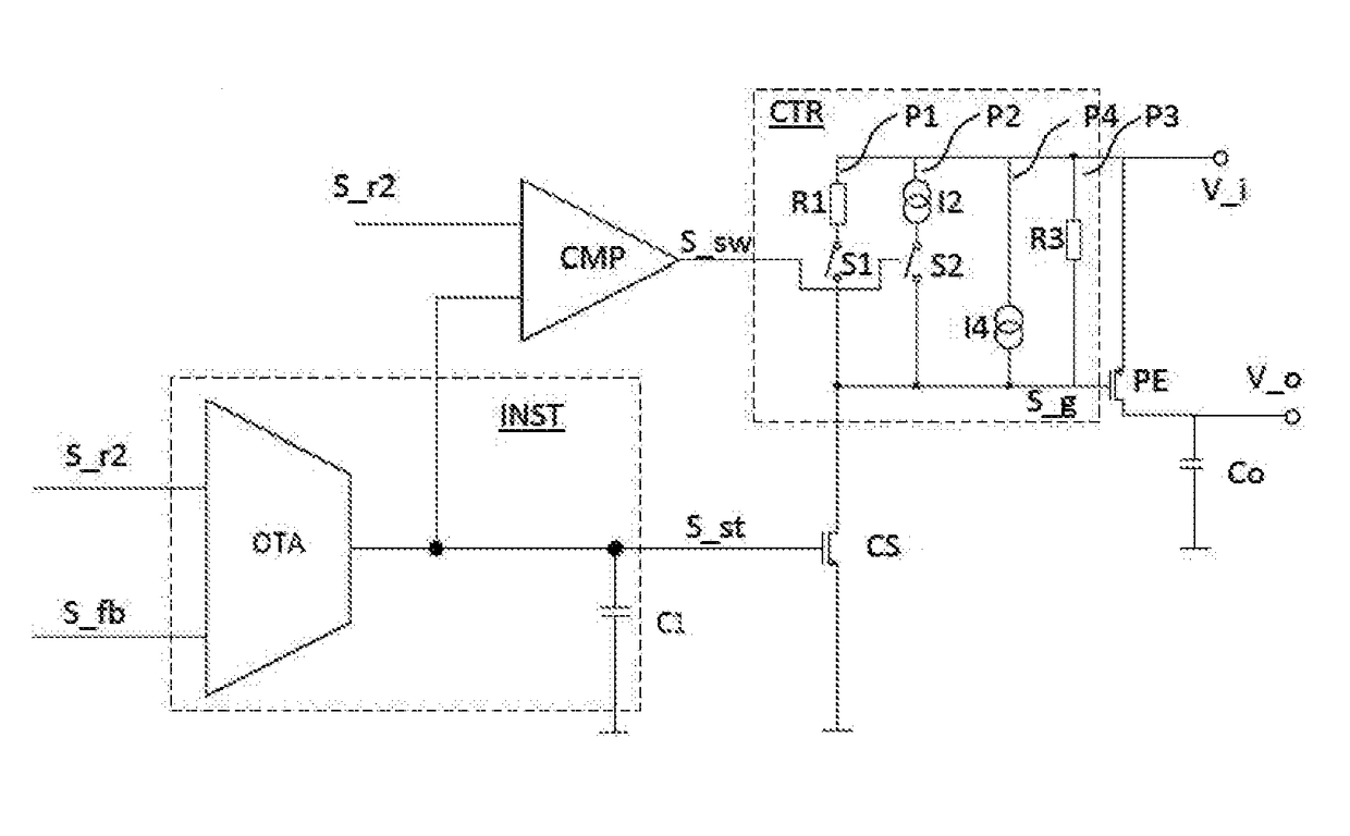
[0056]FIG. 1 shows an exemplary implementation of a low dropout regulator, LDO, circuit according to the improved concept. The LDO circuit comprises a pass element PE, an input stage INST, a current sink CS, a comparator CMP and a control circuit CTR, the control circuit CTR comprising a first current path P1. Optionally, the LDO circuit further comprises a feedback generating circuit FBG, for example a voltage divider, and an output capacitor Co.

[0057]The pass element PE receives an input voltage V_i at an input terminal and a gate signal S_g at a gate control terminal and supplies an output voltage V_o at an output terminal. The output capacitor Co is coupled between the output terminal and a ground terminal. The current sink CS is coupled between the gate control terminal and a ground terminal and is further connected to an output of the input stage INST. The input stage INST receives a first reference signal S_r1 and a feedback signal S_fb. A value of the first reference signal ...


PUM


Abstract

An LDO circuit comprises a pass element, and input stage, a current sink, a comparator and a control circuit. The pass element is configured to generate an output voltage depending on a gate signal and on an input voltage. The input stage is configured to generate a steering signal based on a deviation between a first reference signal and a feedback signal, the feedback signal being based on the output voltage. The current sink is controlled by a steering signal and connected between the gate control terminal and a reference terminal. The comparator is configured to compare the steering signal to a second reference signal and to generate a switch signal based on the comparison. The control circuit comprises a first current path and is configured to suspend, in particular temporarily suspend, the first current path depending on the switch signal.

Description

BACKGROUND OF THE INVENTION[0001]The present disclosure relates to a low dropout regulator, LDO, circuit and to a method for controlling a voltage, in particular an output voltage, of an LDO circuit.[0002]Here and hereafter, the terminology “LDO circuit” comprises all types of low dropout regulator circuits and also charger blocks that are implemented as low dropout regulator circuits.[0003]LDO circuits are building blocks that are widely used for example in power management solutions. For example modern battery powered applications may require a power management which is optimized in view of quiescent current and in performance at the same time. Conventional LDO circuits may suffer from the fact that good transient load performance and low quiescent current of the LDO circuit are hard to achieve at the same time.[0004]Existing LDO circuits may accept high quiescent current consumption. Other existing concepts may be difficult to stabilize and cause an additional current consumption...

Claims


Application Information

Patent Timeline
Patent Type & Authority Applications(United States)
IPC IPC(8): G05F1/575
CPCG05F1/575
Inventor MAYER, MARTINJESSENIG, THOMAS
Owner AMS AG
Why Eureka
Try Eureka