
Hydrocarbon Synthesis Catalyst, Its Preparation Process and Its Use

Active Publication Date: 2018-01-11
SASOL TEKHNOLODZHI PROPRIEHJTEHRI LTD
View PDF1 Cites 0 Cited by
  • Summary
  • Abstract
  • Description
  • Claims
  • Application Information

AI Technical Summary

Benefits of technology

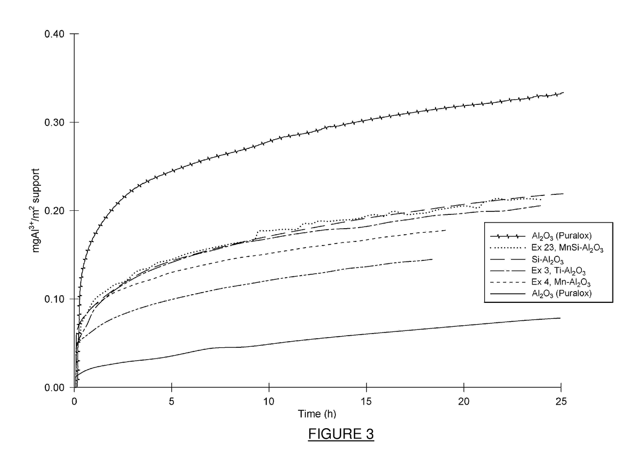
The patent describes a catalyst that can improve the stability and activity of a hydrocarbon synthesis process. This improvement is achieved by adding titanium and manganese to the catalyst. These added materials can reduce the deactivation of the catalyst, which occurs during hydrocarbon synthesis. The effectiveness of the catalyst can be measured after three or 10 days of hydrocarbon synthesis. The added titanium and manganese can also help reduce the amount of methane produced during the synthesis process and can prevent the support material (alumina) from dissolving during the process.

Problems solved by technology

As stated above, a lack of activity stability of a catalyst has the effect that the catalyst deactivates over time and less hydrocarbons are then produced.
However, an increased reaction temperature has the disadvantage that more unwanted methane is formed during the FT synthesis.
Other costly measurements such as increased catalyst loading, catalyst rejuvenation or catalyst reactivation may also be taken to recover the hydrocarbon production.

Method used


Image

  • Hydrocarbon Synthesis Catalyst, Its Preparation Process and Its Use
  • Hydrocarbon Synthesis Catalyst, Its Preparation Process and Its Use
  • Hydrocarbon Synthesis Catalyst, Its Preparation Process and Its Use

Examples


example 15

[0196]The calcined catalyst precursors were reduced prior to Fischer-Tropsch synthesis using pure H2 flowing at 2.0 Nm3 / kgCatalyst / hour at atmospheric pressure. The following heating profile was used, 1° C. / min to 110° C. hold 3 hours followed with, 1° C. / min to 425° C. hold 10 hours. The reduced catalyst was cooled down to room temperature and suspended into molten wax and loaded in a CSTR under an inert gas blanket (argon or nitrogen).

example 16

opsch Synthesis

[0197]The activated and wax protected catalysts, as described in Example 15, were tested for their slurry phase FTS performance in a laboratory micro slurry CSTR at a reactor temperature of 230° C. and a reactor pressure of about 22 bar during which a pure H2 and CO and Ar feed gas mixture was utilised with a ˜5% Ar content and a total feed molar H2 / CO ratio of about 1.8. This reactor was electrically heated and sufficiently high stirrer speeds were employed as to eliminate any gas-liquid mass transfer limitations. The feed gas space velocity was changed such that the syngas conversion was around 78±1%. The water partial pressure was about 10 bar.

Discussion

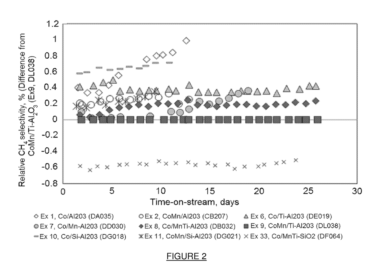
Example 9 (Co / 3.1 g Mn / 100 g Ti—Al2O3) Showed Initial Catalyst Deactivation, However, after 5 Days On-Line the Catalyst Performance Stabilized and Remained Stable Over a 50 Day Period

[0198]FIG. 1 shows the percentage difference in FT rate for Examples 1, 2, 6-8, 10, 11 and 33 relative to Example 9 and can be calcula...

example 17

opsch Synthesis

[0204]The activated and wax protected catalysts, as described in Example 15, for Examples 8 and 9 were tested for their slurry phase FTS performance in a laboratory micro slurry CSTR at a reactor temperature of 230° C. and a reactor pressure of about 19 bar during which a pure H2, CO and Ar feed gas mixture was utilised with a 10% Ar content and a total feed molar H2 / CO ratio of ˜1.5.

[0205]This reactor was electrically heated and sufficiently high stirrer speeds were employed as to eliminate any gas-liquid mass transfer limitations. The feed gas space velocity was changed such that the syngas conversion was around 72±1%. The water partial pressure was about 6 bar.

[0206]Examples 8 and 9 were tested under the conditions described in Example 17. As can be seen from Table 5, Example 8, containing the MnTi support modification and Example 9 (containing Mn as promoter and Ti as support modifier) showed comparable relative FT activities and methane selectivities with time on...


PUM

PropertyMeasurementUnit
Temperatureaaaaaaaaaa
Pressureaaaaaaaaaa
Temperatureaaaaaaaaaa

Abstract

The present invention relates to catalysts, more particularly to a cobalt-containing catalyst composition. The present invention further relates to a process for preparing a cobalt-containing catalyst precursor, a process for preparing a cobalt-containing catalyst, and a hydrocarbon synthesis process wherein such a catalyst is used. According to a first aspect of the invention, there is provided a cobalt-containing catalyst composition comprising cobalt and / or a cobalt compound supported on and / or in a catalyst support; the catalyst composition also including a titanium compound on and / or in the catalyst support, and a manganese compound on and / or in the catalyst support.

Description

TECHNICAL FIELD[0001]The present invention relates to catalysts, more particularly to a cobalt-containing catalyst composition. The present invention further relates to a process for preparing a cobalt-containing catalyst precursor, a process for preparing a cobalt-containing catalyst, and a hydrocarbon synthesis process wherein such a catalyst is used.BACKGROUND ART[0002]Hydrocarbon synthesis from synthesis gas (syngas) containing hydrogen and carbon monoxide in the presence of a Fischer-Tropsch (FT) synthesis catalyst is commonly known as FT synthesis. During the FT synthesis, the syngas is contacted with the FT synthesis catalyst under FT synthesis conditions to produce the hydrocarbons. One type of catalyst which is often used in low temperature FT (LTFT) synthesis comprises an active catalyst component such as Co supported on and / or in a catalyst support such as alumina, silica, titania, magnesia or the like, and the hydrocarbons produced are usually in the form of a waxy hydro...

Claims


Application Information

Patent Timeline
IPC IPC(8): B01J21/06B01J37/08B01J23/889B01J23/34B01J37/02B01J23/89C10G2/00B01J37/04
CPCB01J21/063C10G2/332C10G2/333B01J23/8892B01J23/34B01J23/8913B01J37/04B01J37/0201B01J37/0236B01J37/08B01J23/75B01J37/0244B01J37/18B01J35/19B01J23/8986B01J37/024B01J37/033B01J2523/00B01J2523/31B01J2523/47B01J2523/72B01J2523/828B01J2523/845
Inventor BOTHA, JAN MATTHEUSVISAGIE, JACOBUS LUCASCULLEN, ADAMTALJAARD, JANA HELOISEMEYER, RITA
Owner SASOL TEKHNOLODZHI PROPRIEHJTEHRI LTD
Learn More