
Window glass heating device

Inactive Publication Date: 2017-12-21
TOYOTA JIDOSHA KK
View PDF0 Cites 5 Cited by
  • Summary
  • Abstract
  • Description
  • Claims
  • Application Information

AI Technical Summary

Benefits of technology

The present invention is a device that prevents battery exhaustion by using a window glass heating system. The device creates a closed space between the camera and the window glass, which allows the temperature of the space to easily rise. This prevents fogging on the window glass in front of the camera and reduces the amount of electric power needed to eliminate the fogging.

Problems solved by technology

The camera heating wire consumes a large amount of electric power as compared with electrical components, such as audio devices and car navigation devices.
However, in the device according to the related art, when electric power is not supplied from a power supply source other than the battery due to such reasons as the power generator being in a disabled state, electric power is supplied to the camera heating wire only from the battery.
As a result, a remaining capacity of the battery rapidly decreases.
Accordingly, when electric power is supplied to the camera heating wire only from the battery, there is a possibility that the remaining amount of the battery decreases to the level where the battery is in an insufficient charging state.
Therefore, there is a possibility that battery exhaustion occurs due to such reasons as electric power being supplied from the battery so as to operate other electrical systems (such as an air-conditioner) or electric appliances included in the vehicle while the battery is in the insufficient charging state.
As a result, it becomes possible to lower the possibility that battery exhaustion easily occurs due to such reasons as electric power being supplied from the battery to another electric system (air-conditioner) or electric appliances included in the vehicle while the battery is in the insufficient charging state.

Method used


Image

  • Window glass heating device
  • Window glass heating device
  • Window glass heating device

Examples


first embodiment

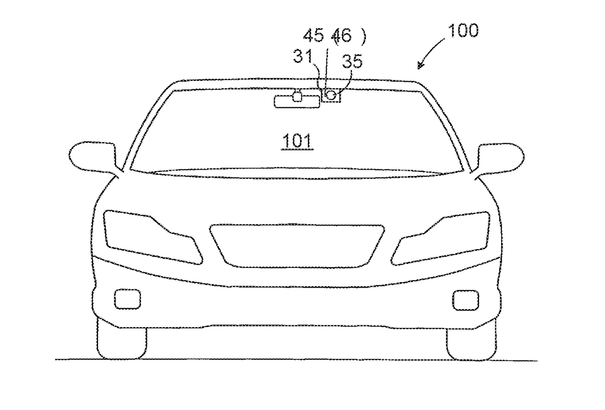
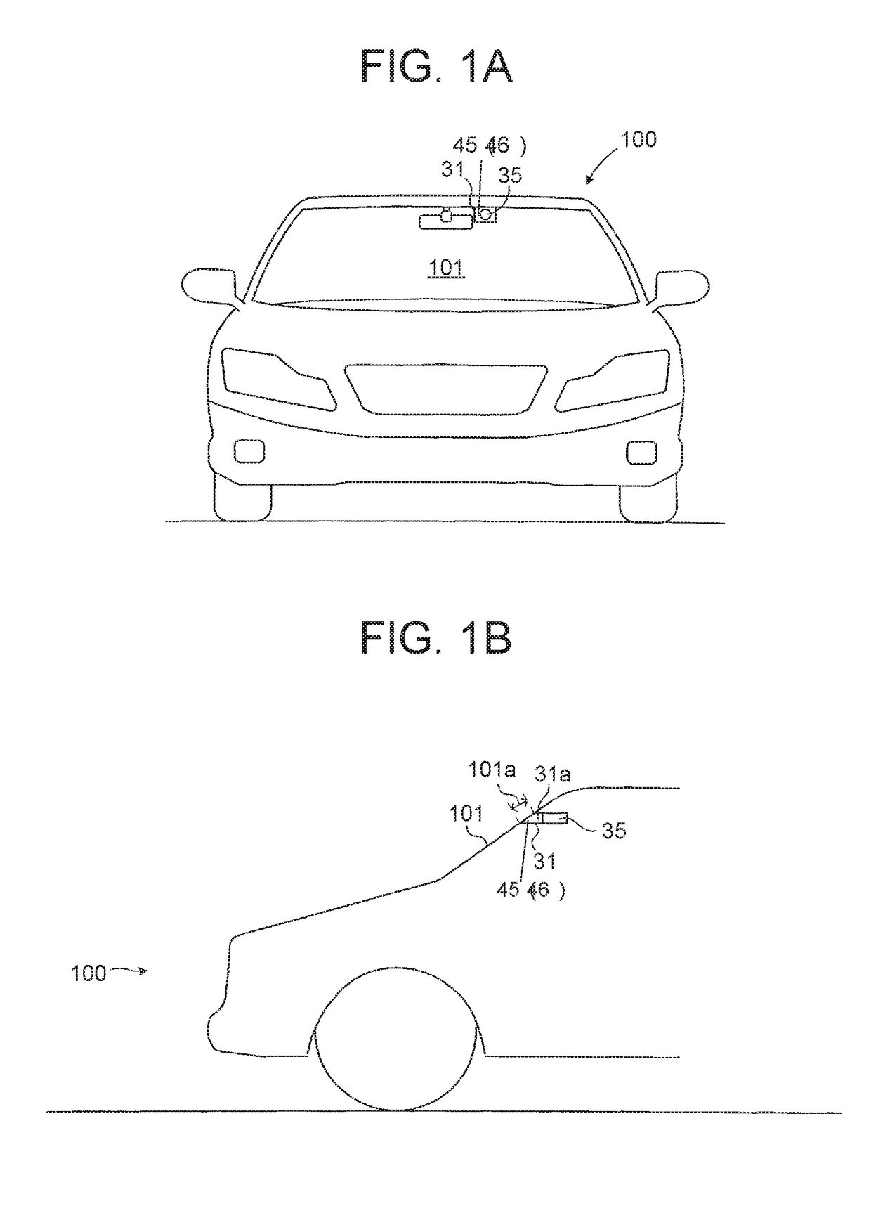
[0036]Hereinafter, a window glass heating device (which is referred to as “first heating device”) according to the first embodiment of the present disclosure will be described with reference to the drawings. The first heating device is applied to a vehicle 100 illustrated in FIGS. 1A and 1B.

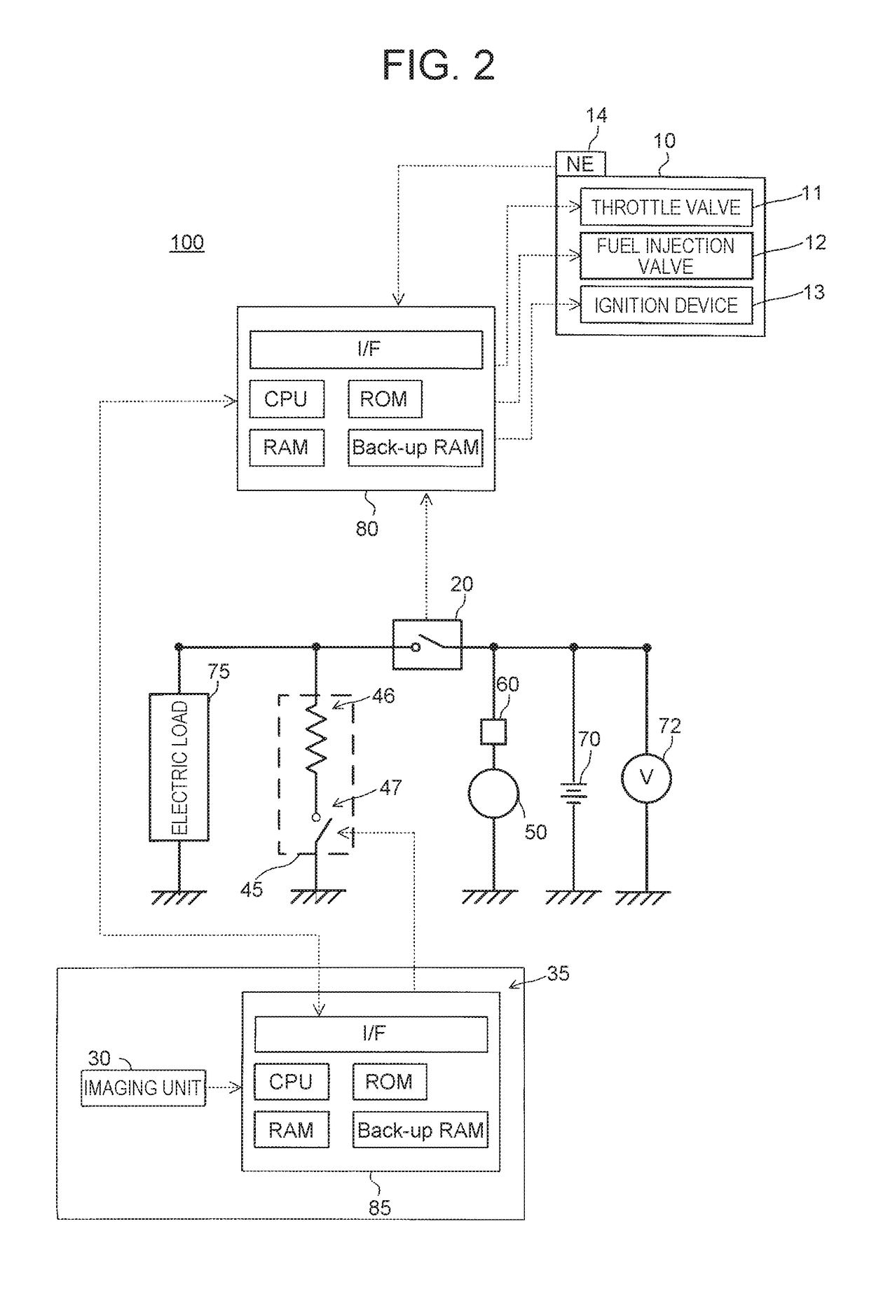
[0037]As illustrated in FIGS. 1A, 1B, and 2, the vehicle 100 includes an internal combustion engine 10, an ignition switch 20, a camera 35, a camera heater 45 as a window glass heating device, an alternator 50 as a power generator, a rectifier 60, a battery 70, a voltage detector 72, an electric load 75, and a main electronic control unit (which is referred to as “main ECU” below) 80.

[0038]The internal combustion engine 10 (which is simply referred to as “the engine 10” below) is a multi-cylinder (four-cylinder in this example) four-cycle spark ignition-type gasoline engine. As illustrated in FIG. 2, the engine 10 includes a throttle valve 11, a fuel injection valve 12, and an ignition device 13....

second embodiment

[0079]A description is given of a window glass heating device (which is referred to as “second heating device” below) according to the second embodiment of the present disclosure. The second heating device is different from the first heating device only in the following point. That is, in the second heating device, the camera CPU in the camera ECU executes a routine illustrated in FIG. 5 in place of the routine illustrated in FIG. 4. Hereinafter, the point of difference is mainly described.

[0080]

[0081]A description is given of specific operation of the second heating device. At the specified timing, the main CPU of the second heating device performs the processing (steps 300 through 350) same as the steps illustrated in FIG. 3. As a result, the main CPU sends out a signal that instructs permission of the heating wire energization control or prohibition of the heating wire energization control to the camera ECU 85.

[0082]At the specified timing, the camera CPU of the second heating de...

third embodiment

[0095]A description is given of a window glass heating device (which is referred to as “third heating device” below) according to the third embodiment of the present disclosure. The third heating device is different from the first heating device only in the following points 1 and 2. That is, 1. the third heating device is applied to a hybrid vehicle including an engine and a generator motor as a driving source. 2. In the third heating device, a hybrid CPU of a hybrid ECU executes a routine illustrated in FIG. 7 in place of the routine illustrated in FIG. 3. Hereinafter, the points of difference are mainly described.

[0096]As illustrated in FIG. 6, a vehicle 200 is a hybrid vehicle including a hybrid system. The vehicle 200 includes an engine 10 and a motor 15 that generate driving force for traveling of the vehicle 200, a ready switch 25, a camera 35, a camera heater 45 as a window glass heating device, a battery 70, a voltage detector 72, and an electric load 75. The vehicle 200 als...


PUM


Abstract

A window glass heating device includes: a battery mounted in a vehicle; a power supply source configured to supply electric power to the battery; a heating wire configured to generate heat upon reception of electric power, the heating wire being disposed to heat a particular part of a window glass of the vehicle; and a control unit configured to control a supply state of electric power supplied to the heating wire. The control unit is configured to: set the supply state to a first state, when the power supply source supplies electric power to the battery; and set the supply state to a second state, when the power supply source does not supply electric power to the battery, the second state being smaller in an amount of electric power supplied to the heating wire than the first state.

Description

CROSS-REFERENCE TO RELATED APPLICATIONS[0001]This application claims priority to Japanese Patent Application No. 2016-120967 filed on Jun. 17, 2016 which is incorporated herein by reference in its entirety including the specification, drawings and abstract.BACKGROUND1. Technical Field[0002]The present disclosure relates to a window glass heating device.2. Description of Related Art[0003]Some vehicles having a camera for a preventive safety system include a heating device (which is referred to as “device according to the related art”) to prevent fogging of a portion of a window glass (for example, a windshield glass or a rear glass) in front of the camera.[0004]The device according to the related art includes a heating wire (which is referred to as “camera heating wire”) for heating the portion of the window glass in front of the camera. The heating wire is energized when energization of the heating wire is requested (see, for example, EP Patent Application Publication No. 2644005).[...

Claims


Application Information

Patent Timeline
IPC IPC(8): H05B3/86H05B1/02
CPCH05B3/86H05B2203/035H05B1/02H05B1/0236
Inventor NAGAE, HAJIME
Owner TOYOTA JIDOSHA KK
Learn More