Channel bonding using k-muxing and multiple-beam antenna

a channel bonding and antenna technology, applied in the field of wireless link throughput and reliability improvement, can solve the problems of limiting channel frequency choices, communication failures or excessively high error rates, network interface cards on host computers, etc., to achieve the effect of improving throughput and reliability of wireless communication, reducing interference and multi-path effects, and increasing data bandwidth

Active Publication Date: 2017-12-21
SPATIAL DIGITAL SYST
View PDF8 Cites 7 Cited by
  • Summary
  • Abstract
  • Description
  • Claims
  • Application Information

AI Technical Summary

Benefits of technology

[0007]A system is provided that enhances the throughput and reliability of wireless communications by providing multi-beam user terminals that exhibit directional discrimination. Multiple wireless communication channels are matched with multiple beams, and the channels are bonded into a single virtual channel, thereby increasing data bandwidth while reducing interference and multi-path effects that can degrade communications.

Problems solved by technology

A network interface card on a host computer, for example, may be limited to a certain maximum data rate.
When channel bonding is attempted over wireless networks, interference between the multiple wireless network cards can cause communication failures or excessively high error rates.
However, of the eleven channels in the 2.4-GHz frequency band of the IEEE 802.11b and g wireless standards, only channels 1 and 11 are spaced sufficiently far apart that they may be used simultaneously without excessive interference, limiting the channel-frequency choices.
As a result of the competition for bandwidth of multiple network users, the overall data throughput may actually decrease.
Such antennas provide little spatial discrimination and are thus not suitable for this purpose.
However, providing a dedicated processor to generate spatially separated beams can add significant complexity and cost.

Method used


Image

  • Channel bonding using k-muxing and multiple-beam antenna
  • Channel bonding using k-muxing and multiple-beam antenna
  • Channel bonding using k-muxing and multiple-beam antenna

Examples


Embodiment Construction

[0036]The invention provides a system for bonding multiple wireless communication channels using multi-beam directional antennas in order to improve communication bandwidth and reliability. In the detailed description that follows, like element numerals are used to indicate like elements appearing in one or more of the figures.

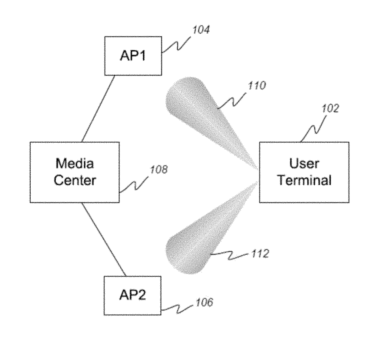
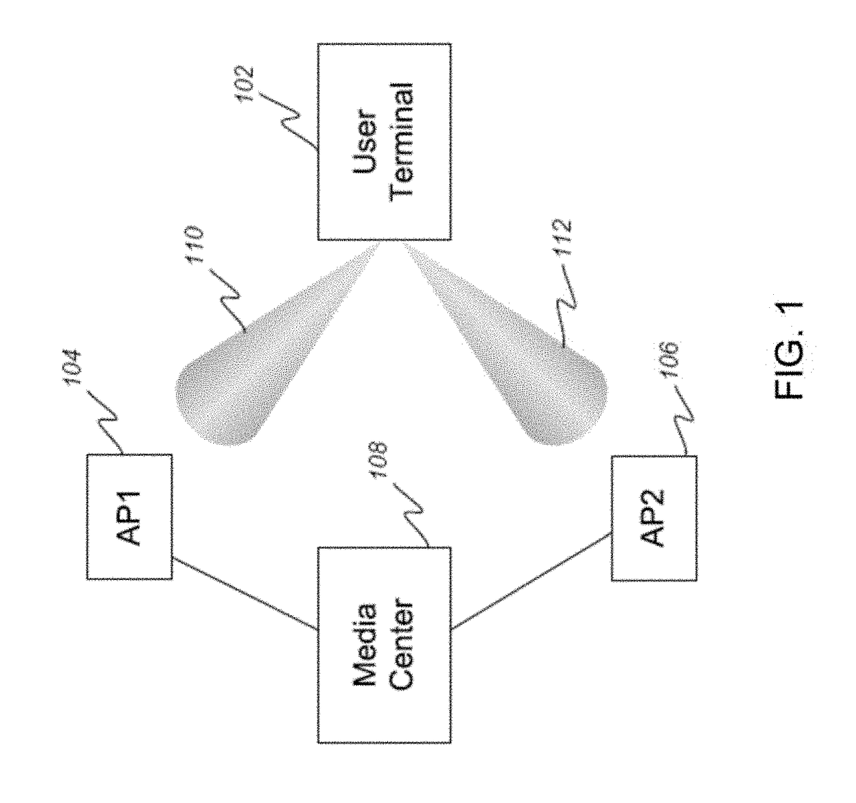
[0037]FIG. 1 depicts a block diagram of an embodiment of a multiple-beam wireless networking system in accordance with the present invention. A media center 108 stores data that it makes available to a wireless network over two spatially separated wireless access points 104 and 106. A user terminal 102 includes a multi-beam antenna capable of pointing narrow beams 110 and 112 in the directions to the two access points 104 and 106, respectively. The user terminal 102 includes a digital-beam-forming (DBF) processor described in more detail below with reference to FIG. 3. The DBF processor allows the construction of two spatially-separated beams that can be indep...


PUM


Abstract

A user terminal for transmitting data to a plurality of access points comprises a pre-processor to pre-process at least one source data stream and a multi-beam antenna. The pre-processor comprises a segmenting device to segment the at least one source data stream into a set of N data sub streams, N being an integer greater than 1; a K-muxing unit to perform a N-to-N K-muxing transform on the N data substreams to generate N K-muxed data streams, each of the N K-muxed data streams being a linear combination of the N data substreams; and a bank of modulators to modulate the N K-muxed data streams to generate N K-muxed signal streams. The multi-beam antenna comprises beam forming networks to transform the N K-muxed signal streams into transmit beams, and an array of antenna elements to transmit the transmit beams to the access points.

Description

RELATED APPLICATIONS[0001]This application is a continuation-in-part of application Ser. No. 13 / 274,782, filed on Oct. 17, 2011, which is a continuation-in-part of application Ser. No. 12 / 122,541, filed on May 16, 2008, now U.S. Pat. No. 8,107,569, issued on Jan. 31, 2012, which claims the benefit of Provisional Patent Application No. 60 / 930,957, filed on May 21, 2007, and the benefit of Provisional Patent Application No. 60 / 930,958, filed on May 21, 2007. This application is related to the following: U.S. Pat. No. 8,953,728 issued on Feb. 10, 2015, entitled “System for Processing Data Streams”; application Ser. No. 12 / 848,953 filed on Aug. 2, 2010, entitled “Novel Karaoke and Multi-Channel Data Recording / Transmission Techniques via Wavefront Multiplexing and Demultiplexing”; and application Ser. No. 14 / 793684 filed on Jul. 7, 2015, entitled “Data transport privacy and redundancy via small UAVs in cooperation”, all of which are expressly incorporated by reference herein in their ent...

Claims


Application Information

Patent Timeline
Patent Type & Authority Applications(United States)
IPC IPC(8): H04W16/28H04W72/04H01Q3/26H01Q3/28H01Q3/36H01Q3/40
CPCH04W16/28H04W72/0453H01Q3/40H01Q3/36H01Q3/28H01Q3/2605H01Q1/007H01Q1/2258H01Q1/2266H01Q3/24H01Q25/00H04J13/0003H04J13/004H04L1/00
Inventor CHANG, DONALD C. D.
Owner SPATIAL DIGITAL SYST
Why Eureka
Try Eureka