Beam alignment

a beam alignment and beam technology, applied in the field of beam alignment, can solve the problems of reducing the level of light, affecting the accuracy of beam alignment, and achieving the wrong alignment, so as to improve stability and reduce the level of light

Active Publication Date: 2017-12-21
FFE
View PDF3 Cites 0 Cited by
  • Summary
  • Abstract
  • Description
  • Claims
  • Application Information

AI Technical Summary

Benefits of technology

The present invention is a method for accurately aligning a beam of light from a detector unit to a reflector in a reflective-type smoke detector. This is done without the need for manual alignment, which is quicker, easier, and more efficient than traditional methods. The method also reduces the incidences of wrong alignment and provides long-term benefits through the life of the installation. By aligning the beam with the reflector, there is a reduction in false alarms caused by movement of the building and identifies unexpected objects through the reflective surface. The size of the beam is controlled through a beam profile that takes into consideration the illuminated area and the amount of illumination. The design of the lens controls the beam profile and divergence angle, which affects the intensity of the beam.

Problems solved by technology

Manual alignment can be a slow and drawn-out process, and it is surprisingly easy, even for professionals using this method, to achieve the wrong alignment—for instance, alignment with a reflective object which is not the reflector per se.
Laser targeting—illumination of the reflector with a visible laser—has led to a reduction in wrong alignment; however, alignment of the laser on the reflector is no guarantee of alignment of the transmitter and the reflector, and the reflector and the receiver.

Method used


Image

  • Beam alignment
  • Beam alignment
  • Beam alignment

Examples


Embodiment Construction

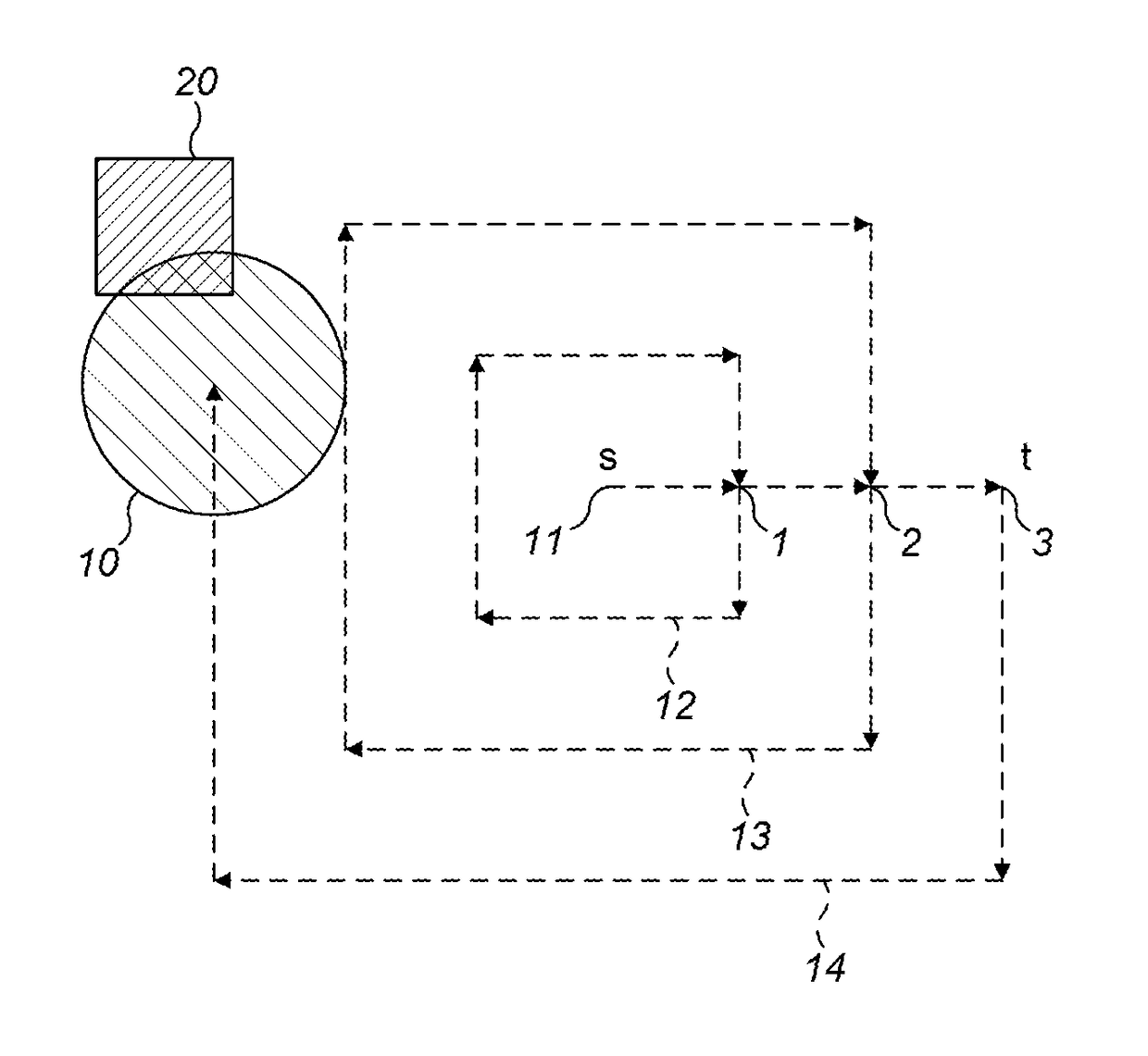
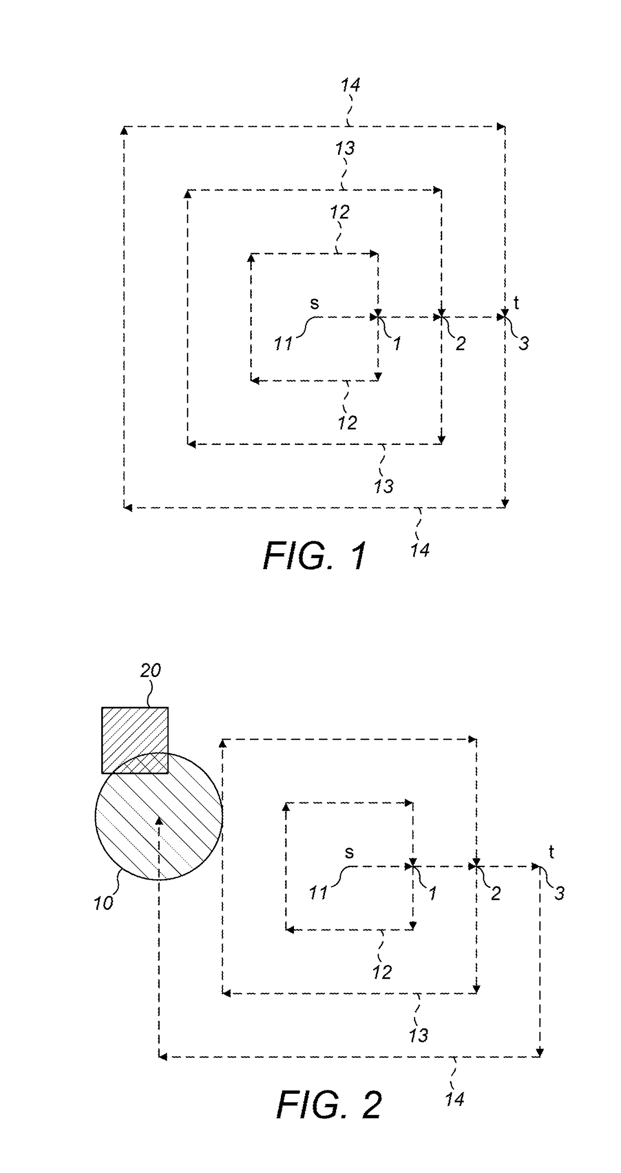
[0061]An overall alignment process has two main steps: firstly, laser targeting of the reflector; and, secondly, an auto-align procedure. In laser targeting, a user remotely maneuvers a detector, using its internal motor, so that an integrated visible laser is pointing at the reflector. The laser is only a rough alignment guide; however, and having the laser on the reflector is no guarantee that the Infrared (IR) beam is also perfectly aligned on the reflector. The auto-align procedure is used to properly align the IR beam on the reflector and has three main steps; search; adjust; and centre. In a preferred embodiment, during the installation procedure, auto-align is automatically initiated after the user has turned off the laser.

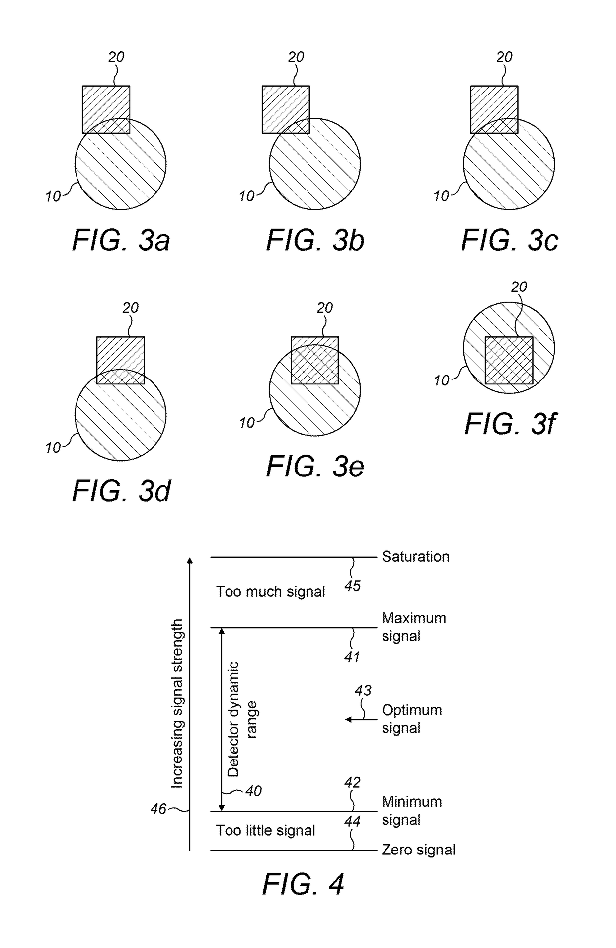
[0062]The auto-align procedure is implemented through an algorithm (which is run by a computer), which algorithm requires a minimum signal level (i.e. a minimum amount of light returned by the reflector) for it to complete correctly. As such, the first cons...


PUM


Abstract

A method for aligning a projected beam on a reflector in a reflective-type beam detector, the method including adjusting the projected beam so as to: project on to substantially all, if not all, of a reflective surface of the reflector; or project on to at least a portion of a reflective surface of the reflector until a constant, or within a predetermined threshold of a constant, signal is received from the reflector; and detecting one or more edges of the reflective surface of the reflector and thereby: centering the projected beam, so as to align an approximate center of the projected beam on, or within a predetermined threshold of, an approximate center of the reflective surface of the reflector; and / or determining a shape or profile of the reflector.

Description

CROSS-REFERENCE TO RELATED APPLICATION[0001]This patent application claims priority from UK Patent Application No. GB1610488.7, filed the 16 Jun. 2016, the disclosure of which is incorporated by reference herein in its entirety.FIELD OF THE INVENTION[0002]The present invention relates to beam alignment. In particular, the invention relates to a method for aligning a projected beam on a reflector in a reflective-type beam detector, a method for searching for and projecting a beam on to a reflector in a reflective-type beam detector, and apparatus associated with the methods.BACKGROUND OF THE INVENTION[0003]In summary, a reflective optical beam smoke detector system has a detector unit, which includes both a transmitter and a receiver, and a retro-reflector. The detector unit and the reflector are placed opposite each other at opposing ends of a volume to be protected and monitored. The transmitter projects a beam, in this example an Infrared (IR) beam, on to the retro-reflector which...

Claims


Application Information

Patent Timeline
IPC IPC(8): G01J5/08G01B11/24G01J5/00G08B17/10G08B29/18
CPCG01J5/0896G01B11/24G08B29/18G01J2005/0048G08B17/10G01J5/0803G08B17/103G08B29/20G01N21/53G08B17/12G08B29/24G01J5/80
Inventor ANDELIN, JACOBDIBDEN, GARETHPERCH, MARCUS
Owner FFE
Why Eureka
Try Eureka