Optical imaging lens
a technology of optical imaging and lens, applied in the field of optical imaging lenses, can solve the problems of increasing the lens length during the operation of vcm, and achieve the effects of reducing the shifting distance of the lens elements, ensuring the imaging quality, and reducing the lens length of the optical imaging lens
- Summary
- Abstract
- Description
- Claims
- Application Information
AI Technical Summary
Benefits of technology
Problems solved by technology
Method used
Image
Examples
first embodiment
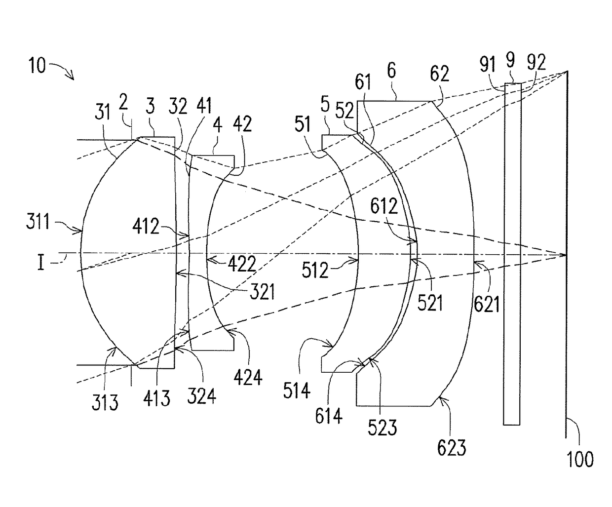
[0076]FIG. 6 is a drawing, schematically illustrating an optical imaging lens, according to an embodiment of the invention. FIG. 7A to FIG. 7D are drawings, schematically illustrating the longitudinal spherical aberration and various kinds of aberration of optical imaging lens, according to an embodiment of the invention. Referring to FIG. 6 first, the optical imaging lens 10 as the invention has a plurality of lens elements from the object side to the image side in order along an optical axis I of the optical imaging lens 10. In the embodiment, the lens elements includes a first lens element 3, a second lens element 4, a third lens element 5, and a fourth lens element 6, arranged in order from the object side to the image side along the optical axis I. In the embodiment, the optical imaging lens 10 includes an aperture 2, a first lens element 3, a second lens element 4, a third lens element 5, a fourth lens element 6, and a filter 9 in order from the object side to the image side a...
second embodiment
[0143]The detailed optical data of the optical imaging lens 10 are shown in FIG. 12, and the effective focal length of the optical imaging lens 10 in the second embodiment is 8.696 mm, the HFOV is 18.617°, the F / # is 2.307, the system length is 6.381 mm, the image height is 2.944 mm.
[0144]As shown in FIG. 13A, it is all of the aspheric coefficients in formula (1) from the object-side surface 31 of the first lens element 3 to the image-side surface 72 of the first additional lens element 7 in the second embodiment.
[0145]Further, relations between all of the essential parameters in the optical imaging lens 10 of the second embodiment are shown in FIG. 46.
[0146]In the embodiment, only one of several gaps in the optical imaging lens 10 can be a variable gap. When the variable gap is changed, it can cause the optical imaging lens 10 to focus onto the object at different object length. In FIG. 13B, when the variable gap is G1a, Ga3, G23, G34 or G4F, it lists the fG value, the EFL, / (fG×F / #...
third embodiment
[0152]The detailed optical data of the optical imaging lens 10 are shown in FIG. 16, and the effective focal length of the optical imaging lens 10 in the third embodiment is 9.000 mm, the HFOV is 17.846°, the F / # is 1.916, the system length is 7.958 mm, the image height is 2.4 mm.
[0153]As shown in FIG. 17A, it is all of the aspheric coefficients in formula (1) from the object-side surface 31 of the first lens element 3 to the image-side surface 82 of the second additional lens element 8 in the third embodiment.
[0154]Further, relations between all of the essential parameters in the optical imaging lens 10 of the third embodiment are shown in FIG. 46.
[0155]In the embodiment, only one of several gaps in the optical imaging lens 10 can be a variable gap. When the variable gap is changed, it can cause the optical imaging lens 10 to focus onto the object at different object length. in FIG. 17B, when the variable gap is G1a, Gab, Gb2, G23, G34 or G4F, it lists the fG value, the EFL / (fG×F / #...
PUM
 Abstract
Description
Claims
Application Information
 - R&D
- Intellectual Property
- Life Sciences
- Materials
- Tech Scout
- Unparalleled Data Quality
- Higher Quality Content
- 60% Fewer Hallucinations
Browse by: Latest US Patents, China's latest patents, Technical Efficacy Thesaurus, Application Domain, Technology Topic, Popular Technical Reports.
© 2025 PatSnap. All rights reserved.Legal|Privacy policy|Modern Slavery Act Transparency Statement|Sitemap|About US| Contact US: help@patsnap.com


