
Organic electroluminescence device

a technology of electroluminescence device and organic material, which is applied in the direction of luminescent composition, organic chemistry, chemistry apparatus and processes, etc., can solve the problems of material deterioration, low heat resistance, and confinement of excitons generated in the luminous layer, and achieves satisfactory efficiency, high efficiency, and effective injection and transport

Active Publication Date: 2017-11-02
HODOGAYA KAGAKU IND
View PDF3 Cites 7 Cited by
  • Summary
  • Abstract
  • Description
  • Claims
  • Application Information

AI Technical Summary

Benefits of technology

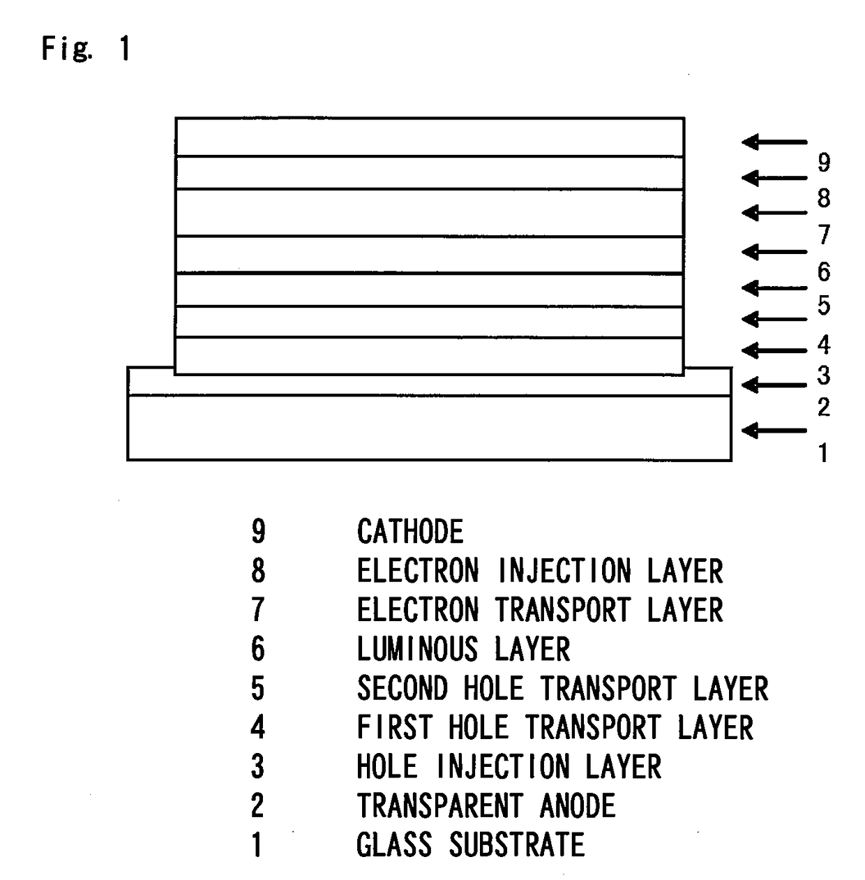
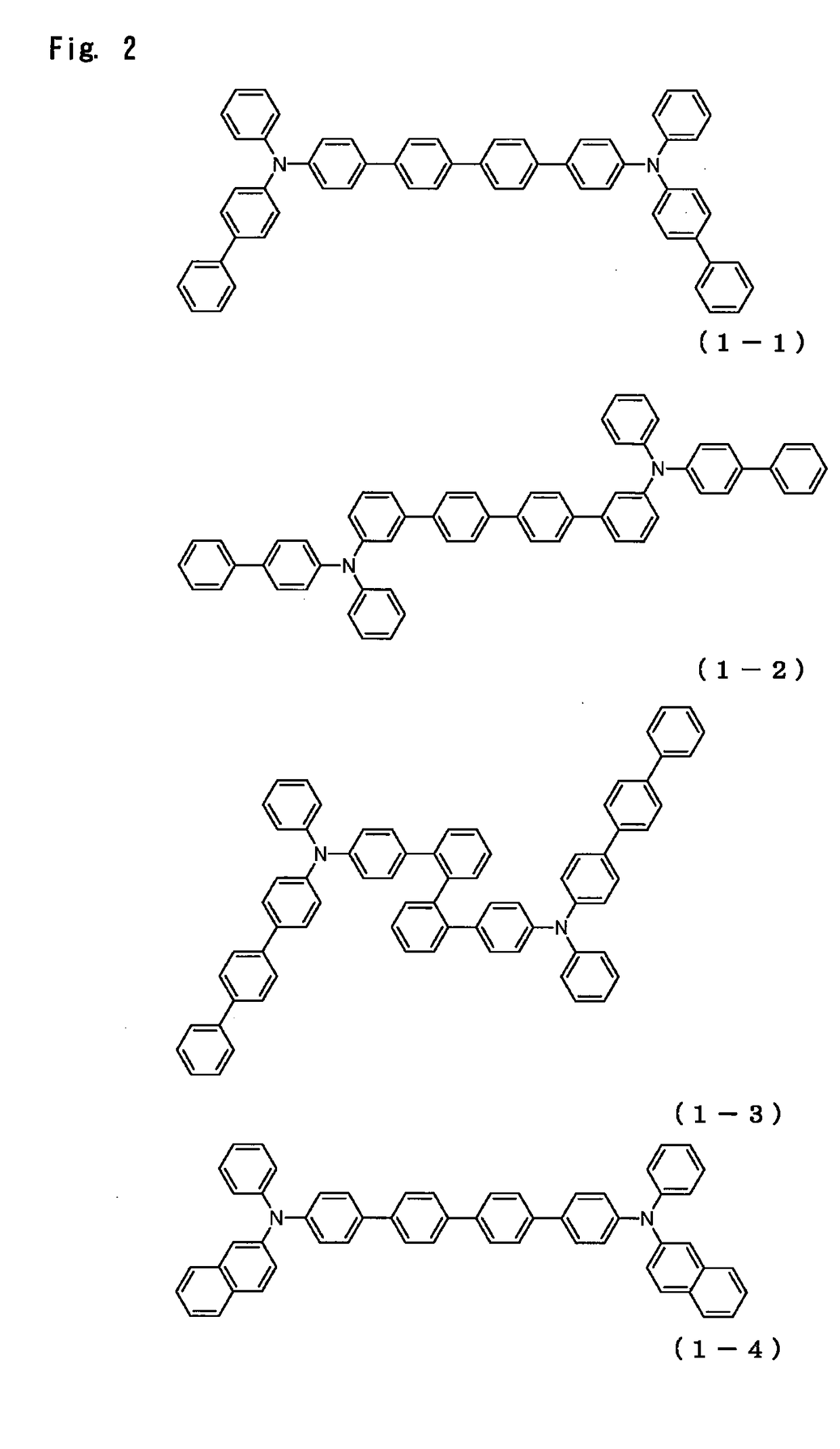
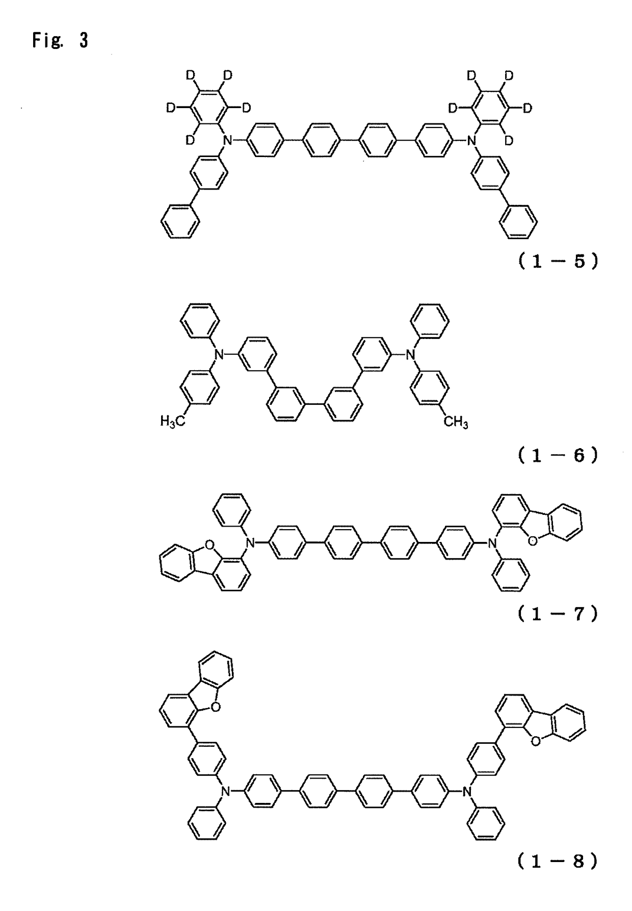
The present invention provides an organic EL device with a high efficiency, low driving voltage, and long life by using a two-layer configuration with a specific hole transport layer and combining an arylamine compound with a specific structure and a pyrimidine derivative with a specific structure, as well as a triarylamine compound with a specific structure as the material of the first hole transport layer. Additionally, the combination of materials resulted in more satisfactory efficiency of holes injection and transport in the luminous layer and improved durability.

Problems solved by technology

Moreover, excitons generated in the luminous layer are confined.
A material with a low heat resistance is thermally decomposed even at a low temperature by heat produced during device driving, and the material deteriorates.
In a material with low amorphousness, crystallization of a thin film occurs even in a short time, and the device deteriorates.
NPD has satisfactory hole transport capacity, but the glass transition temperature (Tg), which is an indicator of heat resistance, is as low as 96° C. and device characteristics degrade due to crystallization under high-temperature conditions.
Further, among the aromatic amine derivatives disclosed in PTL 1 and 2, there are also compounds with an excellent hole mobility of 10−3 cm2 / Vs or higher, but since electron blocking property is insufficient, some of electrons pass through the luminous layer, and no increase in luminous efficiency can be expected.
However, the aromatic amine derivative disclosed in PTL 3 is used as a charge transport material for an electrophotographic photosensitive body and there is no example of application to an organic EL device.
Although heat resistance, luminous efficiency, and the like of devices using these compounds for a hole injection layer or hole transport layer have been improved, the results are still insufficient and further decrease in a driving voltage and increase in luminous efficiency are needed.

Method used


Image

  • Organic electroluminescence device
  • Organic electroluminescence device
  • Organic electroluminescence device

Examples


synthesis example 1

Synthesis of 4,4′″-bis{(biphenyl-4-yl)-phenylamino}-(1,1′:4′,1″:4″,1′″-quaterphenyl)

[0317]

a nitrogen-purged reaction vessel was charged with18.2 g,N-phenyl-N-{4-(4,4,5,5-tetramethyl-1,3,2-dioxaborolan-2-yl)phenyl}-(1,1′-biphenyl-4-yl)amine4,4′-diiodobiphenyl 7.5 g,2M aqueous solution of potassium carbonate  46 mL,toluene  60 mL,andethanol  15 mL,

and a nitrogen gas was passed therethrough for 1 h. Then, 1.1 g of tetrakis(triphenylphosphine)palladium was added, followed by heating, and stirring was performed for 10 h at 72° C. A total of 60 mL of methanol was added after cooling to room temperature. The precipitated solids were collected by filtration and washed with 100 mL of a mixed solution of methanol / water (5 / 1, v / v). Then, 100 mL of 1,2-dichlorobenzene was added and dissolution was performed under heating. The removal of insolubles by filtration was followed by gradual cooling and addition of 200 mL of methanol. The precipitated crude product was collected by filtration. The cru...

synthesis example 2

Synthesis of 4,4″″-bis{(biphenyl-4-yl)-phenylamino}-(1,1′:4′,1″:4″,1′″:4′″,1″″-kinkphenyl)

[0325]

a nitrogen-purged reaction vessel was charged with16.3 g,N-phenyl-N-{4-(4,4,5,5-tetramethyl-1,3,2-dioxaborolan-2-yl)phenyl}-(1,1′-biphenyl-4-yl)amine4,4′-diiodoterphenyl 8.0 g,2M aqueous solution of potassium carbonate  41 mL,toluene  64 mL,andethanol  16 mL,

and a nitrogen gas was passed therethrough for 1 h. Then, 1.0 g of tetrakis(triphenylphosphine)palladium was added, followed by heating, and stirring was performed for 18 h at 72° C. A total of 60 mL of methanol was added after cooling to room temperature. The precipitated solids were collected by filtration and washed with 100 mL of a mixed solution of methanol / water (5 / 1, v / v). Then, 100 mL of 1,2-dichlorobenzene was added and dissolution was performed under heating. The removal of insolubles by filtration was followed by gradual cooling and addition of 200 mL of methanol. The precipitated crude product was collected by filtration. ...

synthesis example 3

Synthesis of 4,4′″-bis{(biphenyl-4-yl)-phenylamino}-(1,1′:3′,1″:3″,1′″-quaterphenyl)

[0333]the reaction was performed under the same conditions as in Synthesis Example 1, except that[0334]3,3′-dibromobiphenyl

was used instead of[0335]4,4′-diiodobiphenyl.

As a result, 16.2 g (yield 91%) of a light yellow powder of 4,4′″-bis{(biphenyl-4-yl)-phenylamino}-(1,1′:3′,1″:3″,1′″-quaterphenyl) (Compound 1-11) was obtained.

[0336]The structure of the resulting light yellow powder was identified using NMR. In 1H-NMR (CDCl3), the following signals of 44 hydrogens were detected.

[0337]δ (ppm)=7.87 (2H)[0338]7.48-7.66 (18H)[0339]7.39-7.48 (4H)[0340]7.29-7.39 (6H)[0341]7.18-7.26 (12H)[0342]7.08 (2H)


PUM

PropertyMeasurementUnit
Electric potential / voltageaaaaaaaaaa
Efficiencyaaaaaaaaaa
Transport propertiesaaaaaaaaaa

Abstract

The present invention provides an organic EL device having at least an anode, a hole injection layer, a first hole transport layer, a second hole transport layer, a luminous layer, an electron transport layer, and a cathode in order of description. The second hole transport layer includes an arylamine compound having a specific structure, and the electron transport layer includes a pyrimidine derivative having a specific structure. The organic EL device of the present invention has a high efficiency, a low driving voltage, and a longer life.

Description

TECHNICAL FIELD[0001]The present invention relates to an organic electroluminescence device, and more particularly to an organic electroluminescence device (abbreviated below as “organic EL device”) using a specific arylamine compound and a specific pyrimidine derivative.BACKGROUND ART[0002]An organic EL device is a light-emitting device, and is brighter, better in visibility, and capable of clearer display than a liquid crystal device. Hence, active researches have been conducted on organic EL devices.[0003]In 1987, C. W. Tang et al. of Eastman Kodak Company developed a laminated structure device sharing various roles for light emission among different materials, thereby imparting practical applicability to organic EL devices. The developed organic EL device is configured by laminating a layer of a fluorescent body capable of transporting electrons, and a layer of an organic substance capable of transporting holes. As a result of injecting positive charges and negative charges into...

Claims


Application Information

Patent Timeline
IPC IPC(8): H01L51/00C07C211/54C07C211/58C07D307/91C09K11/06C07B59/00H01L51/50
CPCH01L51/0059H01L51/5016C07C211/58H01L51/006H01L51/0061C07D307/91C07B59/001C09K11/06H01L51/0072H01L51/0052H01L51/0067H01L51/0077H01L51/5064H01L51/0073C07B2200/05C09K2211/1011C09K2211/1007C09K2211/1014H01L51/0054C09K2211/1018C09K2211/1029H01L51/5072H01L51/5056H01L51/5012C07C211/54C07B59/00C07C211/61C07C2603/18H10K85/622H10K85/615H10K85/631H10K85/636H10K85/633H10K85/654H10K85/6574H10K50/156H10K50/16H10K50/15H10K50/12H10K85/30H10K85/6572H10K50/11H10K2101/10
Inventor HAYASHI, SHUICHIKANDA, DAIZOTOGASHI, KAZUNORI
Owner HODOGAYA KAGAKU IND
Learn More