Planar antenna for mobile satellite applications
a satellite application and antenna technology, applied in the direction of resonant antennas, antenna earthings, radiating elements structural forms, etc., can solve the problem of less efficient antennas and achieve the effect of satisfying efficiency
- Summary
- Abstract
- Description
- Claims
- Application Information
AI Technical Summary
Benefits of technology
Problems solved by technology
Method used
Image
Examples
first embodiment
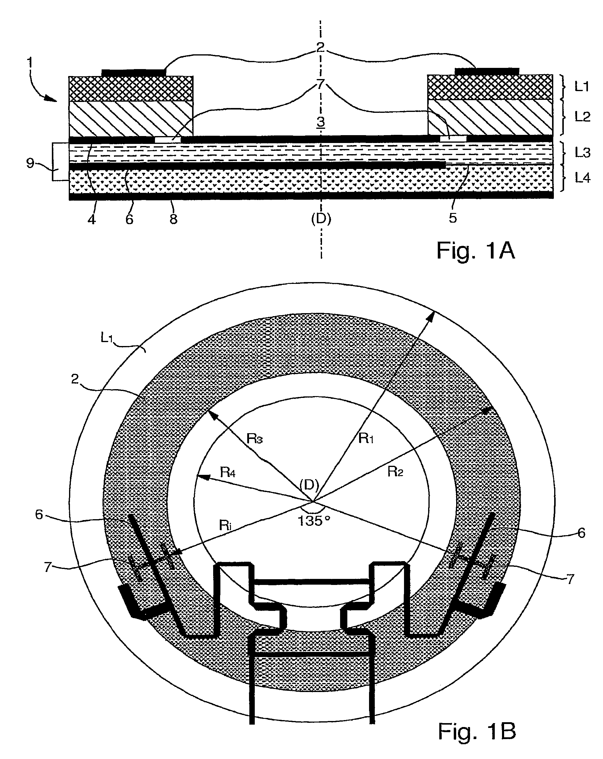
[0035]FIG. 1A is a cross section view of a simple antenna assembly according to the present invention. In terms of structure, antenna assembly 1 preferably occupies a thin disk-shaped or cylindrical volume having a central axis (D) and a height which can be divided into successive layers each being circular or ring-shaped.
[0036]Departing from the top of FIG. 1A and going downwards, antenna assembly 1 comprises an annular patch radiating element 2, preferably printed or etched on an annular epoxy film forming a first layer L1 which secures patch radiating element 2 to the whole antenna assembly. Annular epoxy film L1 is glued on a first dielectric substrate layer L2 formed by a plastic material. Nevertheless, annular epoxy film L1 can be omitted and then patch radiating element 2 is directly glued on plastic layer L2. According to the represented embodiment on FIG. 1A, plastic layer L2 is ring-shaped, a disk-shaped void 3 being let in the middle. However as it will be described herei...
second embodiment
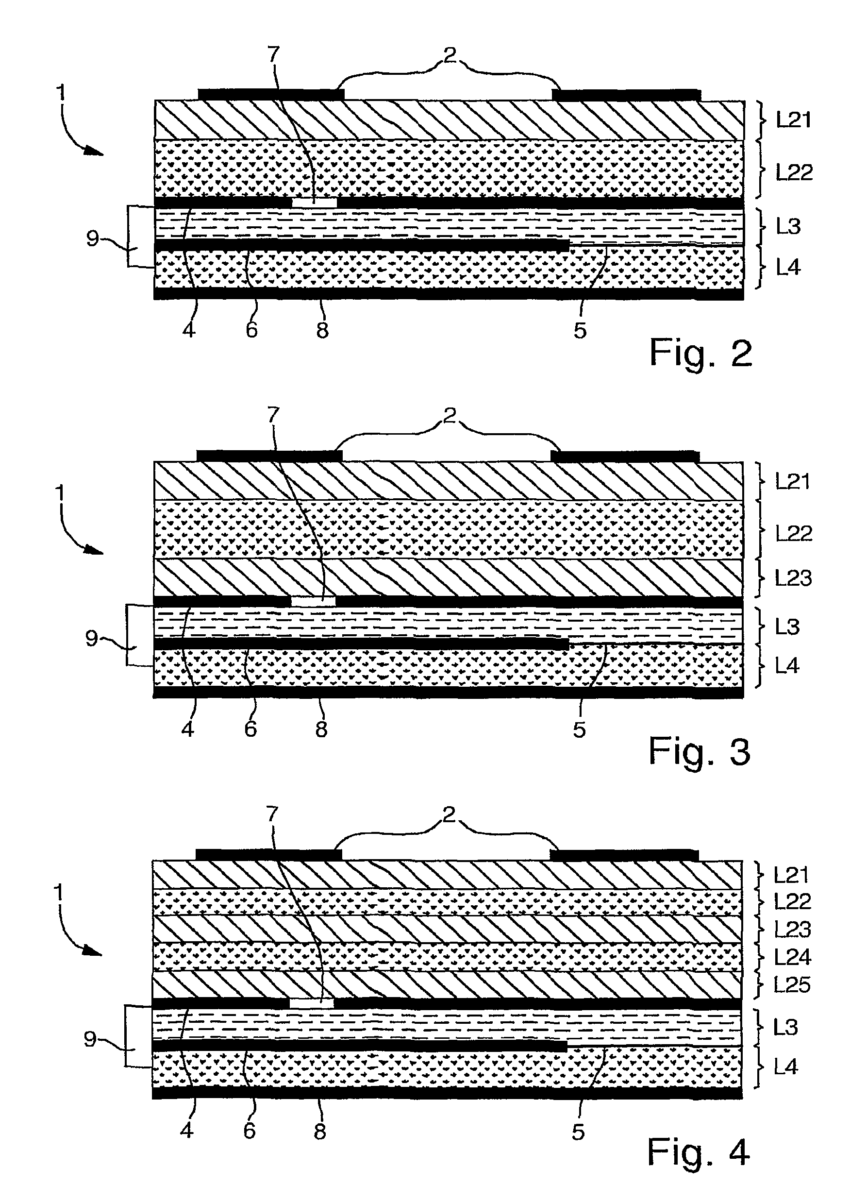
[0051]FIG. 2 is a cross section view of a simple antenna assembly according to a first variant of the present invention. All common elements with FIG. 1A will not be described in detail again.
[0052]The main difference between the previously described first embodiment and the second one relies on the dielectric substrate disposed between annular patch radiating element 2 and electrically conducting ground plane 4. In fact in the second embodiment, it is provided with a dielectric substrate based on sandwiched dielectric layers L21 and L22 composed of materials with different characteristics. The ad-hoc composition of dielectric layers L21 and L22 with different permittivity and thickness allows to synthesize the permittivity of the dielectric substrate between annular patch 2 and first ground plane 4, and therefore to optimize the size of the antenna and its performances.
[0053]Previous studies have shown that the use of high permittivity substrates can be used not only to reduce the ...
third embodiment
[0071]Given below is an array with the dimensions of the different layers (L1, L21-L23 and L3-L4) according to a preferred example of the above described Also given below are the dielectric constants (Dc), also called dielectric permittivity, of the different layers.
[0072]
LayerMaterialThickness (mm)DcL1Epoxy (optional0.54.4layer)L21Plastic only or0.8 to 52.3Plastic + EpoxyL22Epoxy + Foam0.1 to 2-34.4or Epoxy onlyL23Plastic0.8 to 52.3L3PTFE0.53L4Foam (or air)1 a 51.05
[0073]It is to be noted that electromagnetic-coupling is less influenced than slot-coupling by the support of the antenna (e.g. the car-top) and therefore the height of layer L4 could be further reduced.
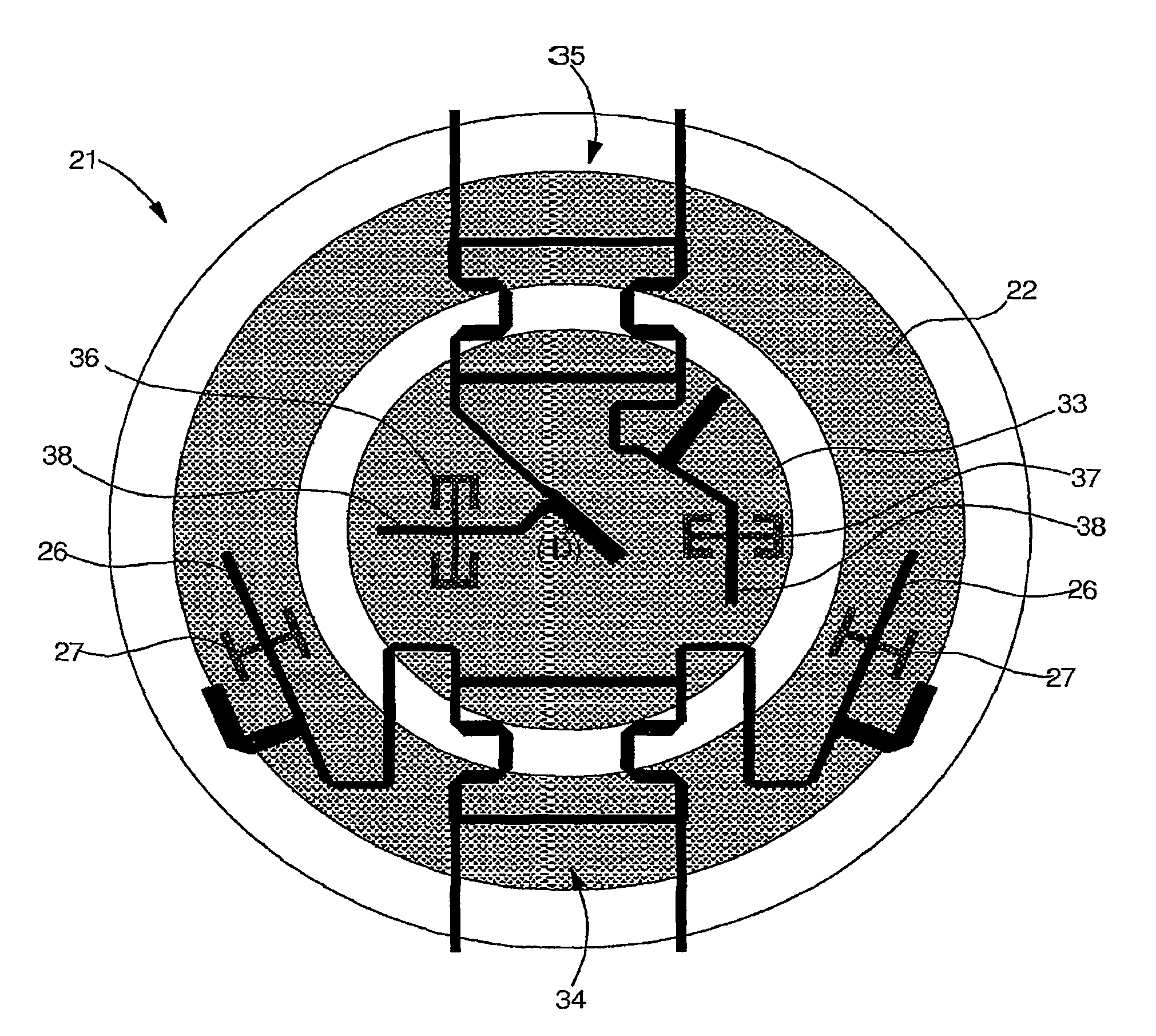
[0074]FIG. 7 is a partial top view of a first multi-system antenna assembly 21 according to any of the preceding embodiments of the present invention. In this multi-system antenna, it is provided with antennas for at least two applications and preferably more than two. A very interesting feature is the overall size of su...
PUM
 Abstract
Description
Claims
Application Information
 - R&D
- Intellectual Property
- Life Sciences
- Materials
- Tech Scout
- Unparalleled Data Quality
- Higher Quality Content
- 60% Fewer Hallucinations
Browse by: Latest US Patents, China's latest patents, Technical Efficacy Thesaurus, Application Domain, Technology Topic, Popular Technical Reports.
© 2025 PatSnap. All rights reserved.Legal|Privacy policy|Modern Slavery Act Transparency Statement|Sitemap|About US| Contact US: help@patsnap.com


