
Assembly for aircraft, and aircraft

A technology for aircraft and components, applied in the field of aircraft, engine installation, and commercial aircraft, can solve problems such as increased clearance, rotor wear at the tip of the blade, and reduced engine life.

Active Publication Date: 2015-06-24
AIRBUS OPERATIONS (SAS)
View PDF8 Cites 8 Cited by
  • Summary
  • Abstract
  • Description
  • Claims
  • Application Information

AI Technical Summary

Problems solved by technology

[0009] Although the solution is satisfactory overall, there is still room for improvement in terms of engine deformation
Indeed, engine deformations observed during operation, in particular deformations caused by buckling along the engine's transverse axis, lead to blade tip rotor wear
This wear increases the clearance between the blade and the casing surrounding the blade, reducing the overall efficiency of the engine and reducing the life of the engine

Method used


Image

  • Assembly for aircraft, and aircraft
  • Assembly for aircraft, and aircraft
  • Assembly for aircraft, and aircraft

Examples


Embodiment Construction

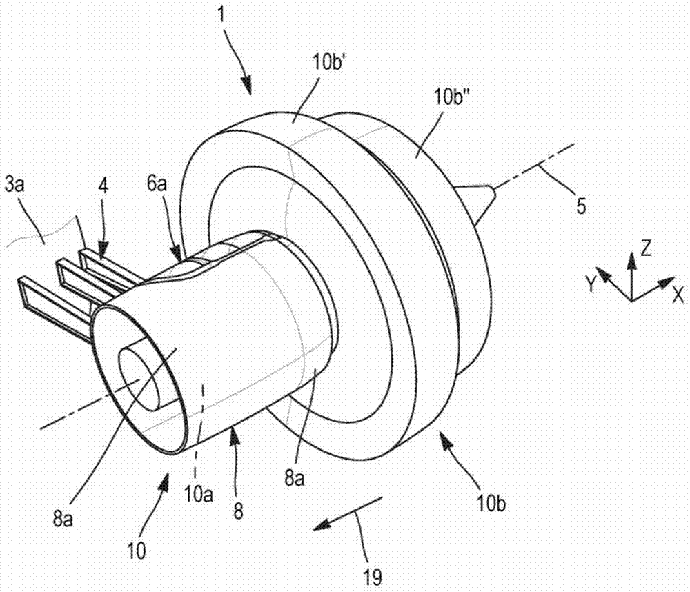
[0038] Refer to attached figure 1 , the attached figure 1 An aircraft 200 is depicted comprising a wing 2 fixed to a fuselage 3 at the rear of which an assembly 1 according to the invention is arranged. The assembly 1 comprises a rear section 3a of the fuselage, an engine 10 and mounting struts 4 for mounting the engine 10 on the rear section 3a of the fuselage. It should be noted that within the assembly 1 two engines 10 are each arranged on one side of the rear fuselage section 3 a respectively. However, in the remainder of the description, only the interaction between one of the two engines 10 and the rear fuselage section 3a will be described.

[0039] figure 2 Component 1 is depicted in enlarged form.

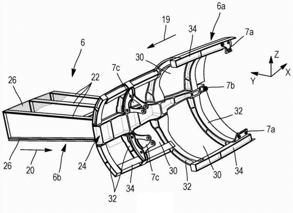
[0040] As mentioned above, this assembly 1 comprises the rear section 3a of the fuselage, the engine 10, the compartment 8 surrounding the engine, and the mounting struts 4 for mounting the engine 10 on the rear section 3a of the fuselage. The engine 10 is here prefe...


PUM


Abstract

To minimize distortion of the engine, the invention provides an assembly (1) for aircraft comprising a rear portion (3a) of an aircraft, a motor (10), a nacelle (8) and a suspension pylon (4) of the engine on the rear part, the assembly also comprising hooking means (7) of the engine on a rigid structure (6) of the mast, the fastening means comprising two engine mounts (7a) designed to ensure the recovery of axial forces of thrust generated by the engine .; According to the invention, the rigid structure (6) of the mast has a first portion (6a) surrounding in part the motor, said first portion comprising an outer skin forming a portion of an outer aerodynamic surface of the nacelle (8), and the two engine mounts (7a) are arranged diametrically opposite at the rear of the rigid structure (6), being connected to the first portion (6a).

Description

technical field [0001] The invention relates to the field of mounting an engine on the rear section of an aircraft, preferably on the rear section of the fuselage or on a vertical empennage. [0002] The invention relates more particularly to the installation of an engine in which the receiver of the engine is a pair of counter-rotating propellers arranged at the rear of the gas generator. This type of engine is often referred to as an "open rotor" engine in a "propeller configuration". [0003] The invention also relates to an aircraft equipped with such an assembly. The invention is preferably applicable to commercial aircraft. Background technique [0004] With some types of aircraft, the engines are fixed at the rear section of the fuselage rather than being suspended below the wing structure as is the more conventional case. Alternatively, the engine may be fixed to the vertical tail of the aircraft, again at the rear section of the aircraft. [0005] The engine is ...

Claims


Application Information

Patent Timeline
IPC IPC(8): B64D27/26
CPCB64D27/20B64D27/40
Inventor 朱利安·吉耶莫塞巴斯蒂安·阿尔比杰罗姆·科尔马格罗帕斯卡尔·波梅乔纳森·布兰克托马斯·罗比利奥托比亚斯·舍斯特伦
Owner AIRBUS OPERATIONS (SAS)
Learn More