Optical transmission module

Inactive Publication Date: 2005-04-28
PANASONIC CORP
View PDF1 Cites 4 Cited by
  • Summary
  • Abstract
  • Description
  • Claims
  • Application Information

AI Technical Summary

Benefits of technology

[0013] Therefore, an object of the present invention is to provide an optical transmission module and method capable of suppressing occurrence of multiplexed reflection light, thereby making it possible to easily carry out an optical coupling operation at low cost.
[0023] In the optical transmission module of the present invention, the loss generator, which has an attenuation factor determined based on an extinction ratio of a modulation signal, is provided to attenuate reflection light in a transmission path, thereby making it possible to provide a low-cost optical transmission module, which ensures a practically satisfactory efficiency, without providing an optical isolator component. Also, in the optical transmission module, the intensity of light is adjusted by the loss generator. Thus, it is possible to realize the optical transmission module using an optical mounting technique with such accuracy as employed for an ordinary module.
[0024] In the case where the attenuation factor of the loss generator is set based on an extinction ratio, etc., the attenuation factor can be determined based on a known value(s), making it possible to readily set the attenuation factor of the loss generator.
[0025] Also, in the case where the attenuation factor of the loss generator and a bias level and modulation amplitude of a modulation signal are set based on the intensity of output light and the quality of reflection light, the attenuation factor can be automatically adjusted so as to attenuate the reflection light in the transmission path. Also, it is possible to stabilize an output of the optical transmission module.
[0026] Also, in the case where the intensity ratio of the intensity of the reflection light to the intensity of the output light is adjusted so as to become a value based on, for example, an extinction ratio, the attenuation factor can be set so as to be consistent with a target value based on a known value. Thus, it is possible to readily set the target value of the attenuation factor of the loss generator, making it possible to realize a low-cost optical transmission module, which ensures a practically satisfactory efficiency, without providing an optical isolator component.
[0027] Also, the optical transmission method of the present invention achieves an effect similar to that achieved by the above-described optical transmission module.

Problems solved by technology

However, in the case of ordinary middle- or long-distance high-speed baseband optical transmission, where a narrow spectrum width is required, an interference noise level is increased, and therefore the usefulness of such a semiconductor laser is low.
Regarding the optical transmission / reception system including the optical isolator 104, the cost of the optical isolator 104 is high, and therefore it is difficult to reduce the cost of the optical transmission module including the optical isolator 104.
That is, there is a difficulty in optically coupling the semiconductor laser with the optical fibers, resulting in an increase in cost of the optical transmission module.

Method used


Image

  • Optical transmission module
  • Optical transmission module
  • Optical transmission module

Examples


first embodiment

[0036] (First Embodiment)

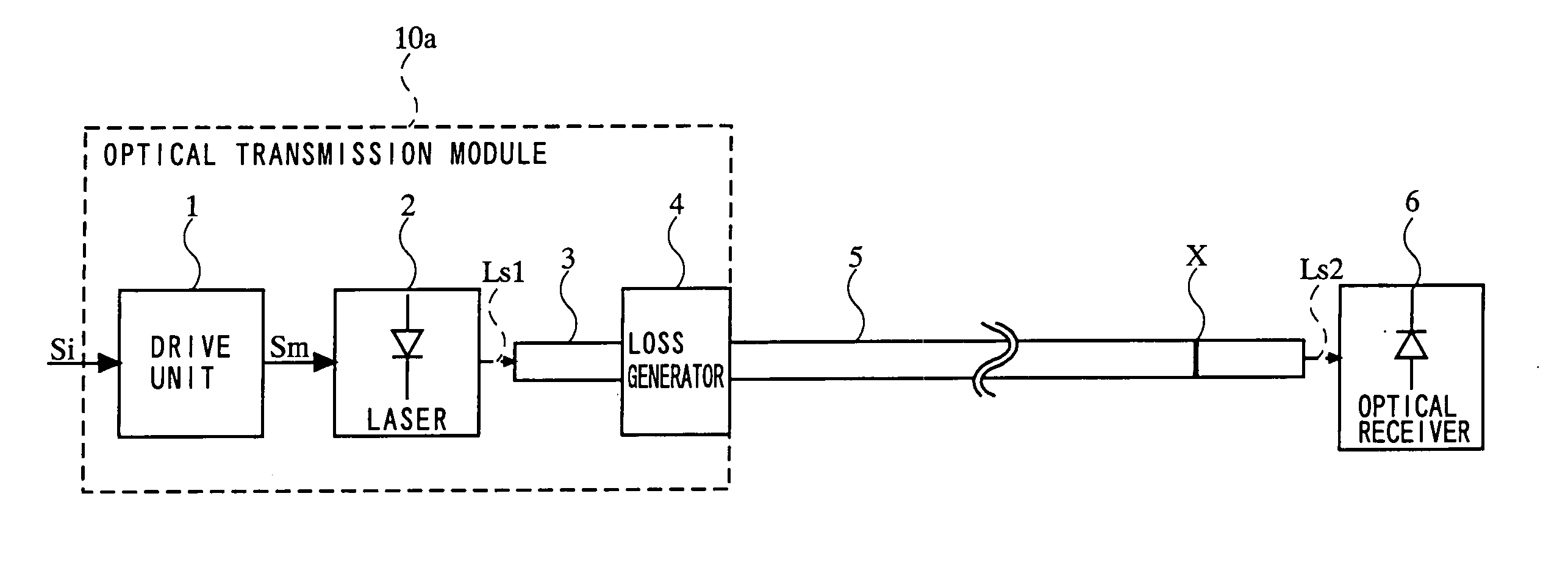
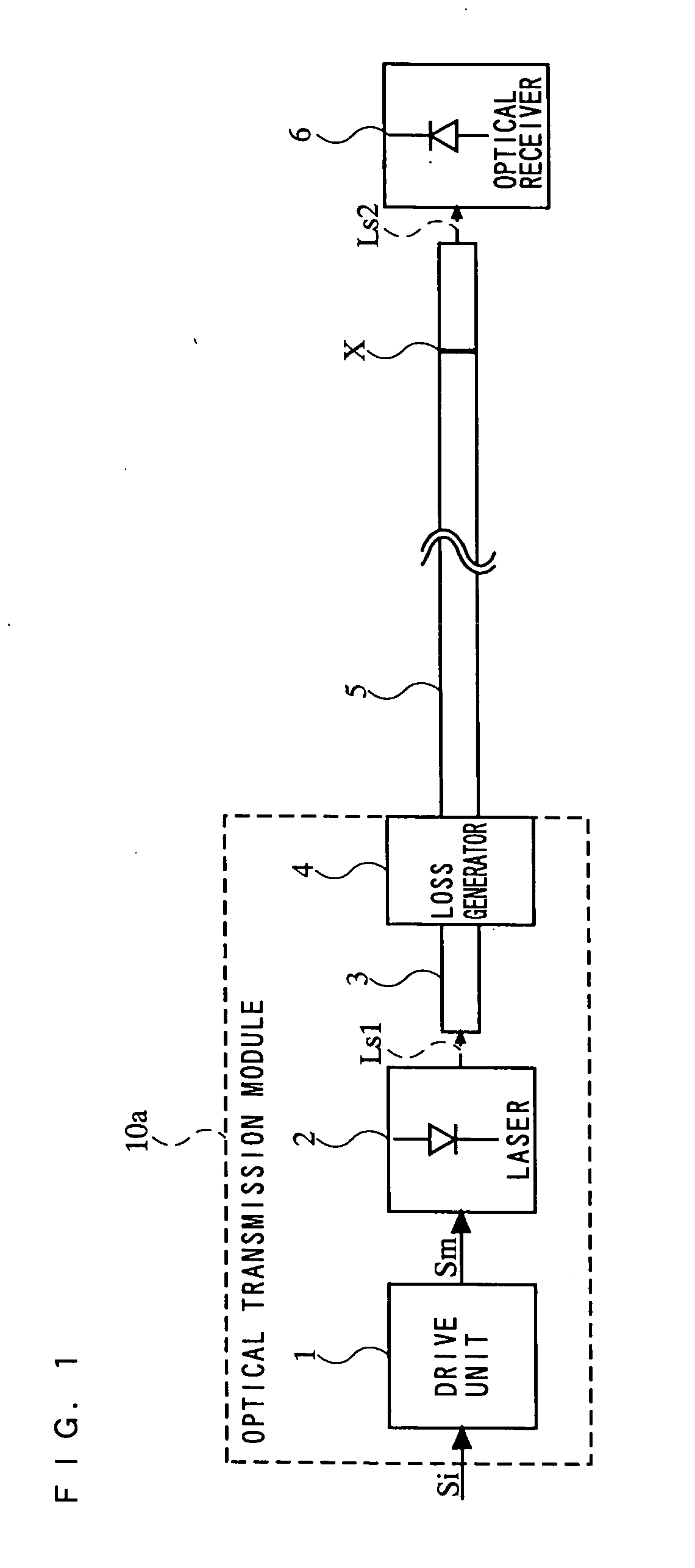
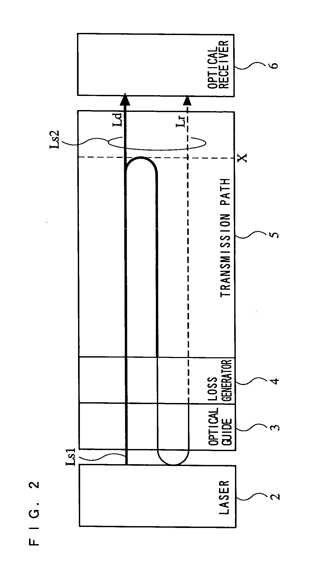
[0037] Referring to FIGS. 1 and 2, an optical transmission / reception system including an optical transmission module according to a first embodiment of the present invention is described. FIG. 1 is a block diagram showing a schematic structure of the optical transmission / reception system including the optical transmission module according to the first embodiment, and FIG. 2 is a diagram used for explaining how an optical signal propagates through the optical transmission / reception system shown in FIG. 1.

[0038] In FIG. 1, the optical transmission / reception system includes a drive unit 1, a semiconductor laser 2, an optical guide 3, a loss generator 4, a transmission path 5, and an optical receiver 6. The drive unit 1, the semiconductor laser 2, the optical guide 3, and the loss generator 4 compose an optical transmission module 10a according to the first embodiment.

[0039] The drive unit 1 receives an input signal Si, and converts it into a modulation signal...

second embodiment

[0046] (Second Embodiment)

[0047] Referring to FIG. 3, an optical transmission / reception system including an optical module according to a second embodiment of the present invention is described. In the optical transmission module described in the first embodiment, a loss generator having a predetermined attenuation factor is provided for maintaining the transmission quality related to multiple reflection noise. However, signal light outputted from the optical transmission module is attenuated by the loss generator. The optical transmission / reception system described in the second embodiment stabilizes an output from the optical transmission module. FIG. 3 is a block diagram showing a schematic structure of the optical transmission / reception system.

[0048] In FIG. 3, the optical transmission / reception system includes a drive unit 11, a semiconductor laser 12, an output light detection unit 13, a reflection light detection unit 14, a comparison unit 15, a variable loss generator 18, t...


PUM


Abstract

An object of the present invention is to provide an optical transmission module and method capable of suppressing occurrence of multiplexed reflection light, thereby making it possible to easily carry out an optical coupling operation at low cost. A loss generator 4 having an attenuation factor determined based on an extinction ratio of a modulation signal Sm is provided to attenuate reflection light in a transmission path 5, thereby making it possible to provide a low-cost optical transmission module 10, which ensures a practically satisfactory efficiency, without providing an optical isolator component. Also, in the optical transmission module 10, the intensity of light is adjusted by the loss generator 4. Thus, it is possible to realize the optical transmission module using an optical mounting technique with such accuracy as employed for an ordinary module.

Description

BACKGROUND OF THE INVENTION [0001] 1. Field of the Invention [0002] The present invention relates to an optical transmission module and method which directly intensity-modulates a semiconductor laser to carry out optical transmission, and more particularly to an optical transmission module connected to a transmission path, which includes a reflection point having a predetermined reflection coefficient, and an optical transmission method for setting a reflectivity condition of the optical module for carrying out optical transmission. [0003] 2. Description of the Background Art [0004] Conventionally, through the rapid spread of the Internet, the transmission capacity of data communication networks has been increased. While the transmission capacity has been increased, middle- and long-distance systems, typified by metro networks, have been becoming bottlenecks of the communication networks, increasing the need for techniques and optical devices which economically realize faster middle...

Claims


Application Information

Patent Timeline
IPC IPC(8): G02B6/26H04B10/04
CPCG02B6/266
Inventor FURUSAWA, SATOSHIFUSE, MASARU
Owner PANASONIC CORP
Why Eureka
Try Eureka