
Hand-operated striking tool enabling vibrations to be reduced, and method for manufacturing

a technology of hand-operated and striking tools, which is applied in the direction of metal-working hand tools, metal-working apparatus, metal-working apparatus, etc., can solve the problems of musculoskeletal troubles, lasting damage to his physical integrity, loss of sensation, etc., and achieve satisfactory efficiency, reasonable cost, and significant reduction of vibrations

Active Publication Date: 2014-11-25
FISKARS FRANCE
View PDF12 Cites 6 Cited by
  • Summary
  • Abstract
  • Description
  • Claims
  • Application Information

AI Technical Summary

Benefits of technology

The invention is a striking tool that reduces vibrations compared to existing tools, while still maintaining efficiency and affordability. The tool has a unique design with a handle, an intermediate shaft, and a flexible link part. These features absorb and isolate vibrations, resulting in improved user experience and performance. The penetration of the shaft into the tube is facilitated by the flexible link part, which breaks the vibration bridge. The terminal region of the tip is free inside the tube, allowing the shaft to vibrate in an air zone, further isolating vibrations. The shaft's rigidity also increases the frequency of vibrations, improving overall user satisfaction.

Problems solved by technology

This is accompanied by musculo-skeletal troubles, such as pains at the level of the carpal tunnel or a loss of sensation at the finger-tips.
These ailments can lead to the operator having to temporarily stop working or can cause lasting damage to his physical integrity.
It has however been observed that the solutions presented above do not provide a satisfactory solution to the vibration problem occurring when striking tools are used.

Method used


Image

  • Hand-operated striking tool enabling vibrations to be reduced, and method for manufacturing
  • Hand-operated striking tool enabling vibrations to be reduced, and method for manufacturing
  • Hand-operated striking tool enabling vibrations to be reduced, and method for manufacturing

Examples


Embodiment Construction

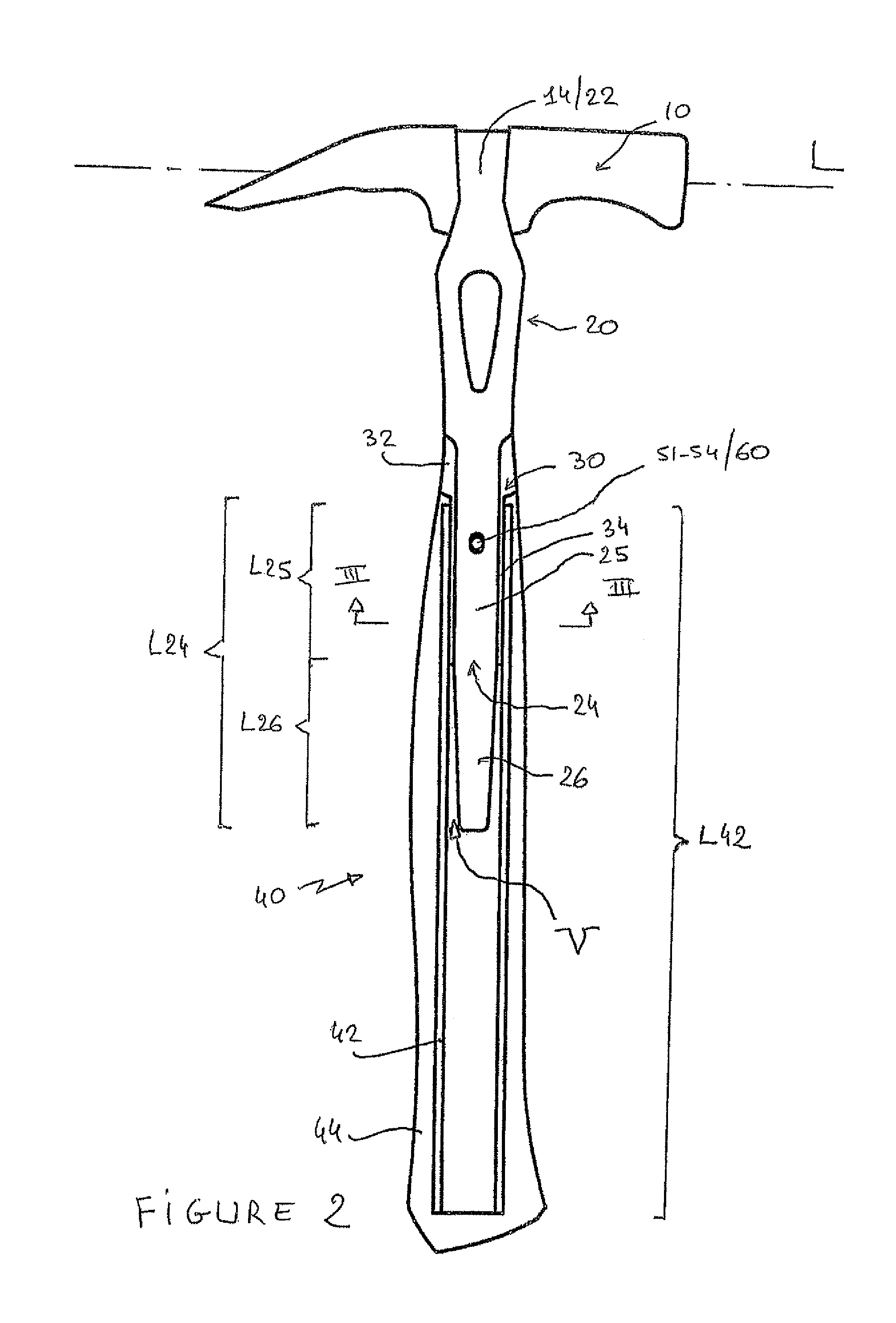
[0024]The different figures represent an example of a striking tool according to the invention, which is in this instance a hammer. This tool 1 is essentially composed of a striking head 10, an intermediate shaft 20, a joining part 30 designed to dampen vibrations, and a gripping handle 40.

[0025]Head 10 is of conventional structure, suitable for the required function of the hammer. In the example, it is of elongate shape, being provided with prongs 12 to pull nails or tacks out. A housing 14 enabling the shaft to be inserted is further drilled out in this head.

[0026]Shaft 20, which extends in the extension of handle 40, joins the latter to head 10. It is made from a first material called rigid material, which is in particular made from metal, in particular from steel. This shaft 20 has a body 21, terminated by a barrel 22 designed to be crimped inside the above-mentioned housing 14. Opposite this barrel, the body is extended, via a rim 23, by a tip 24 designed to enter into a tube b...


PUM

PropertyMeasurementUnit
depth of penetrationaaaaaaaaaa

Abstract

This tool, which is in particular a hammer, comprises a gripping handle, a striking head, and an intermediate shaft extending the handle and supporting the head, whereas the handle comprises a tube in which the shaft partially extends, this tube and this shaft being made from a rigid material presenting a first hardness.This shaft has a radial area bearing against the tube, with interposition of a link part, for absorbing vibrations, made from flexible material presenting a second hardness that is much lower than the first hardness, and a free terminal area, not covered by the link part, radially separated from the walls of the tube so as to be able to vibrate freely in an internal volume of the tube.

Description

BACKGROUND OF THE INVENTION[0001]The invention relates to a hand-operated striking tool, i.e. able to be used without a motor. Within the scope of the invention, such a tool is in particular but not exclusively a hammer, a club, a sledge hammer or a mallet.STATE OF THE ART[0002]In usual manner, a striking tool of hammer type is composed of a handle enabling it to be gripped by the user, to which a striking head is joined. It can be conceived that, when repeated striking actions are performed, such a tool generates substantial vibrations which are transmitted directly to the operator. This is accompanied by musculo-skeletal troubles, such as pains at the level of the carpal tunnel or a loss of sensation at the finger-tips. These ailments can lead to the operator having to temporarily stop working or can cause lasting damage to his physical integrity.[0003]In order to remedy this problem of the occurrence of vibrations, the STANLEY company has proposed a hammer forged in a single part...

Claims


Application Information

Patent Timeline
Patent Type & Authority Patents(United States)
IPC IPC(8): B25D1/00B25D1/12B25D1/04B25G1/01
CPCB25G1/01Y10T29/49826Y10T29/49925
Inventor DESCOMBES, FREDERICLUGRIN, DIDIERPEPIN, FABRICE
Owner FISKARS FRANCE
Learn More